1 module 1 - s, Ignal, Nput – Red Lion DP5T User Manual
Page 11: Arameters
11
5.1 MODULE 1 - S
IGNAL
I
NPUT
P
ARAMETERS
(
)
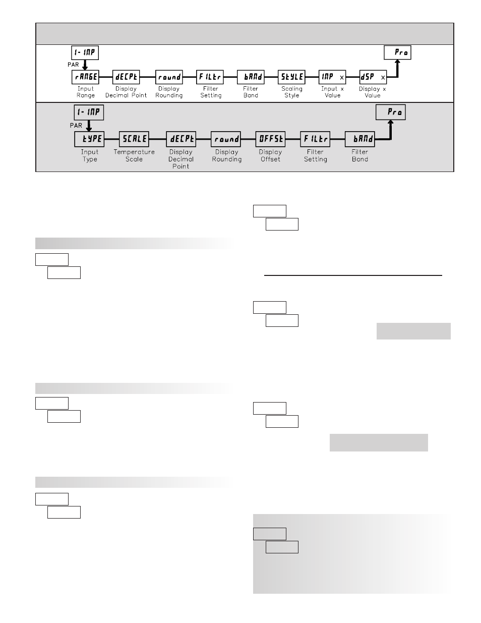
PARAMETER MENU
DP5T PARAMETER MENU
ª
«
DP5D INPUT RANGE
Select the input range that corresponds to the external signal. This selection
should be high enough to avoid input signal overload but low enough for the
desired input resolution. This selection and the position of the Input Range
Jumper must match.
±2.0000 A
2A
SELECTION
RANGE
RESOLUTION
RANGE
RESOLUTION
SELECTION
300u
20u
±300.00 V
±20.000 V
±200.00 mA
2u
±2.0000 V
±200.00 mV
±20.000 mA
±2.0000 mA
±200.00 µA
200uA
Refer to the appropriate Input Range for the selected
meter. Use only one Input Range, then proceed to Display
Decimal Point.
ª
«
DP5P INPUT RANGE
Select the input range that corresponds to the external signal.
±10.000 V
±20.000 mA
RANGE
RESOLUTION
SELECTION
DP5T INPUT TYPE
DP5T: TEMPERATURE DISPLAY OFFSET*
ª
«
TEMPERATURE SCALE
Select the temperature scale. This selection applies for Input, MAX, MIN,
and TOT displays. This does not change the user installed Custom Units
Overlay display. If changed, those parameters that relate to the temperature
scale should be checked.
°C
°F
ª
«
0.000
0.0000
0.00
0.0
0
DISPLAY DECIMAL POINT
Select the decimal point location for the Input, MAX and MIN displays. (The
TOT display decimal point is a separate parameter.) This selection also affects
,
and
parameters.
These selections are not
available for DP5T.
These bottom selections are not
available for DP5T.
ª
«
Select the input type that corresponds to the input sensor. For RTD types,
check the RTD Input Jumper for matching selection. For sensor verification and
testing, use the direct readout modes.
rES-H
Direct ohms range low
Direct ohms range high
N TC
B TC
Cu427
Direct mV range
RTD copper 10
Ω
S TC
R TC
SELECTION
TYPE
TYPE
SELECTION
Ni672
Pt392
RTD nickel 672
RTD platinum 392
K TC
Pt385
RTD platinum 385
C TC
J TC
E TC
T TC
tc-t
ª
«
DISPLAY ROUNDING*
100
50
20
10
5
2
1
Rounding selections other than one, cause the Input Display to ‘round’ to the
nearest rounding increment selected (ie. rounding of ‘5’ causes 122 to round to
120 and 123 to round to 125). Rounding starts at the least significant digit of
the Input Display. Remaining parameter entries (scaling point values, etc.) are
not automatically adjusted to this display rounding selection.
ª
«
The temperature display can be corrected with an offset value. This can be
used to compensate for probe errors, errors due to variances in probe placement
or adjusting the readout to a reference thermometer. This value is automatically
updated after a Zero Display to show how far the display is offset. A value of
zero will remove the affects of offset.
to