Program counter module 17, Count modes 17 – Red Lion LEGEND User Manual
Page 19
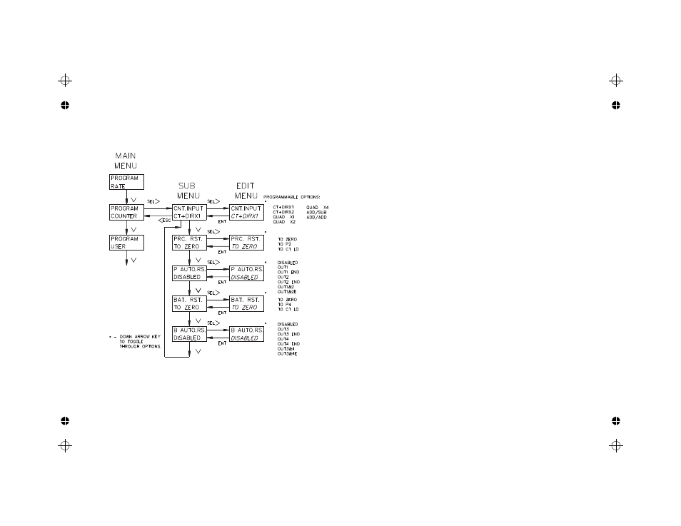
PROGRAM COUNTER MODULE
In the Counter module, the count mode, reset action, and automatic reset
capability are selected. The following flowchart shows only the Counter portion:
COUNT MODES
There are seven available count modes, which can be used with the separate
external Inhibit terminal. Input A signal is used for count and the rate input. Input
B is used in combination with Input A for Count Control Direction, Quadrature
counting, Anti-coincidence Add/Subtract or Anti-coincidence Add/Add
counting applications.
CT+DIRX1 (X1 COUNTING WITH DIRECTION)
The unit will count one count on every negative edge of the input signal at
Input A. The direction of the count is determined by the logic state of Input B.
A high level at Input B will cause the unit to count in a positive direction. A
low level will cause the unit to count in a negative direction. The rate display is
NOT affected by the logic state of Input B.
CT+DIRX2 (X2 COUNTING WITH DIRECTION)
The unit will count one count on every negative edge of the input signal and
one count on every positive edge of the input signal at Input A. In this mode,
the input signal is effectively doubled. The direction of the count is
determined by the logic state of Input B. A high level at Input B will cause the
unit to count in a positive direction. A low level will cause the unit to count in a
negative direction. The rate display is NOT affected by the state of Input B.
QUAD X1 (QUADRATURE X1)
Quadrature counting modes are primarily used in positioning and anti-jitter
applications. The reason this mode works is due to the manner in which the
two incoming pulses are positioned relative to each other. The pulse signal on
Input B is shifted 90° away from the pulse signal at Input A. These two signals
are processed by the Legend as follows:
Input A serves as the count and rate input, while Input B serves as the
quadrature input. For quadrature with single edge counting, the counter will
count in a positive direction when Input A is a negative going edge and Input B
is at a low level. The counter will count in a negative direction when Input A is
a positive going edge and Input B is at a low level. All transitions on Input A
are ignored when Input B is at a high level. These logic rules provide the basis
for anti-jitter operation which will prevent false counts from occurring due to
back-lash, vibration, chatter, etc.
-17-