Vaisala HMP230 User Manual
Page 29
HMP230 SERIES
M210225en-B
User's Guide
23
Power supply
24 VDC
24 VAC (see page 23)
with power supply module
115/230 VAC
Output signals
0...20 mA, 4...20 mA
0...1 V, 0...5 V, 0...10 V
Power supply ground (-) is connected to the housing with parallel connection
of 15 nF capacitor and 300 k
Ω
resistor.
See Appendix 2 on how to connect the power supply module to the
transmitter.
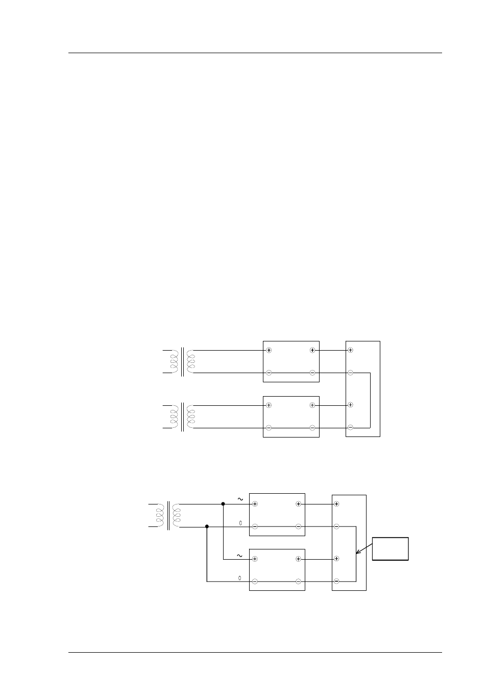
3.4.1. Connection to a 24 VAC supply
The HMP230 transmitters can also be connected to a 24 VAC supply without
an external rectifier. However, when more than one transmitter is connected to
one 24 VAC transformer, a common loop is formed and there is an increased
risk of a short-circuit. To avoid this, always use separate floating supply for
each transmitter (see Figure 21 A). However, if several transmitters have to
share one transformer, the phase (
∼
) must always be connected to + connector
in each transmitter (see Figure 21 B).
24 VAC
HMP230 transmitter
HMP230 transmitter
Controller
shared
common
24 VAC
24 VAC
HMP230 transmitter
HMP230 transmitter
Controller
B) COMMON LOOP FORMED - NOT RECOMMENDED!
A) NO COMMON LOOP FORMED - RECOMMENDED
s
u
p
p
ly
v
o
lt
a
g
e
s
ig
n
a
l
o
u
tp
u
t
s
u
p
p
ly
v
o
lt
a
g
e
s
ig
n
a
l
o
u
tp
u
t
s
u
p
p
ly
v
o
lt
a
g
e
s
u
p
p
ly
v
o
lt
a
g
e
s
ig
n
a
l
o
u
tp
u
t
s
ig
n
a
l
o
u
tp
u
t
line
Figure 21 Connecting the transmitters to a 24 VAC supply