Vaisala HMP230 User Manual
Page 12
HMP230 SERIES
User's Guide
M210225en-B
6
NOTE
During installation the sensor head must not be unsol-
dered from and again resoldered to the main printed
board of the transmitter. This procedure may damage
the humidity calibration of the transmitter.
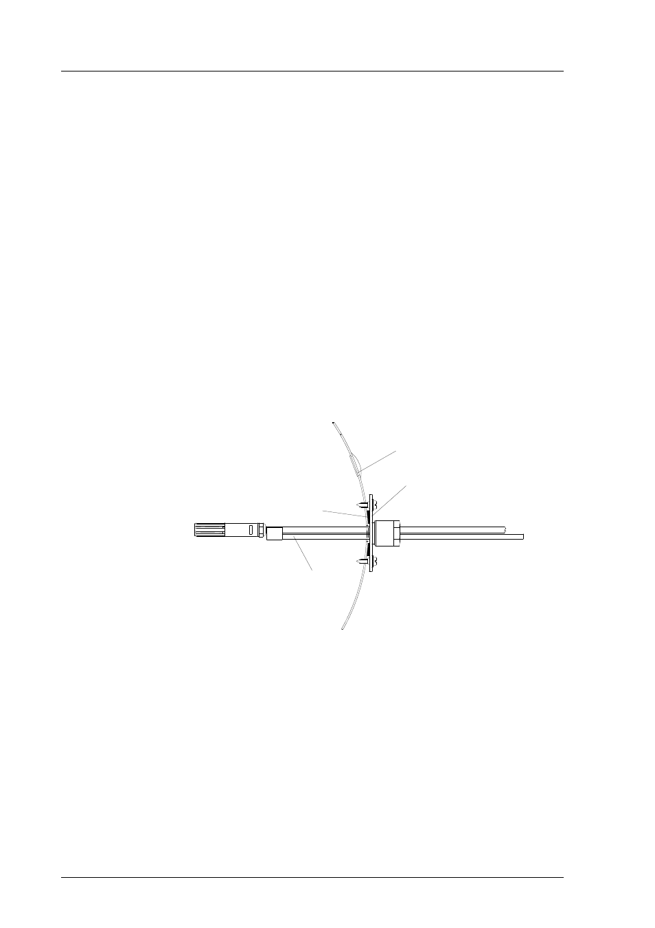
3.2.3. HMP233 transmitter
The HMP233 can be installed in ducts and channels with the help of the in-
stallation kit available; the kit consists of a flange, a supporting bar for the
sensor head cable and screws for attaching the flange to the wall of a duct.
With the help of the installation kit the distance between the sensor head and
the channel wall can be easily adjusted. The range of adjustment is 100...320
mm; the distance is measured from the tip of the sensor head to the flange.
supporting bar
sealing
flange
a plugged hole for reference
measurements
duct wall
Figure 3
Installing the sensor head of the HMP233 in a channel with
the help of flange and supporting bar.