JKS 9100 User Manual
Page 3
JKS9100
JKS Switchblade Swaybar Installation
Page 3
Remove front swaybar from vehicle.
3. PREPARE FRONT CROSS mEmBER
The SwitchBlade Swaybar mounts through the tubular
crossmember that connects the chassis rails together im-
mediately forward of the steering box. Crossmember must
be intact and free of damage in order to install this product.
Inspect the inside surface at each end of the
crossmember for any debris or deformation that
could interfere with installation of Torsion Bar
Bushings (D).
Clean any mud, dirt, rust, burs, slag, or other de-
bris from inside ends of crossmember.
HINT: A die grinder with sanding wheel or similar tool is
useful for removing stubborn debris.
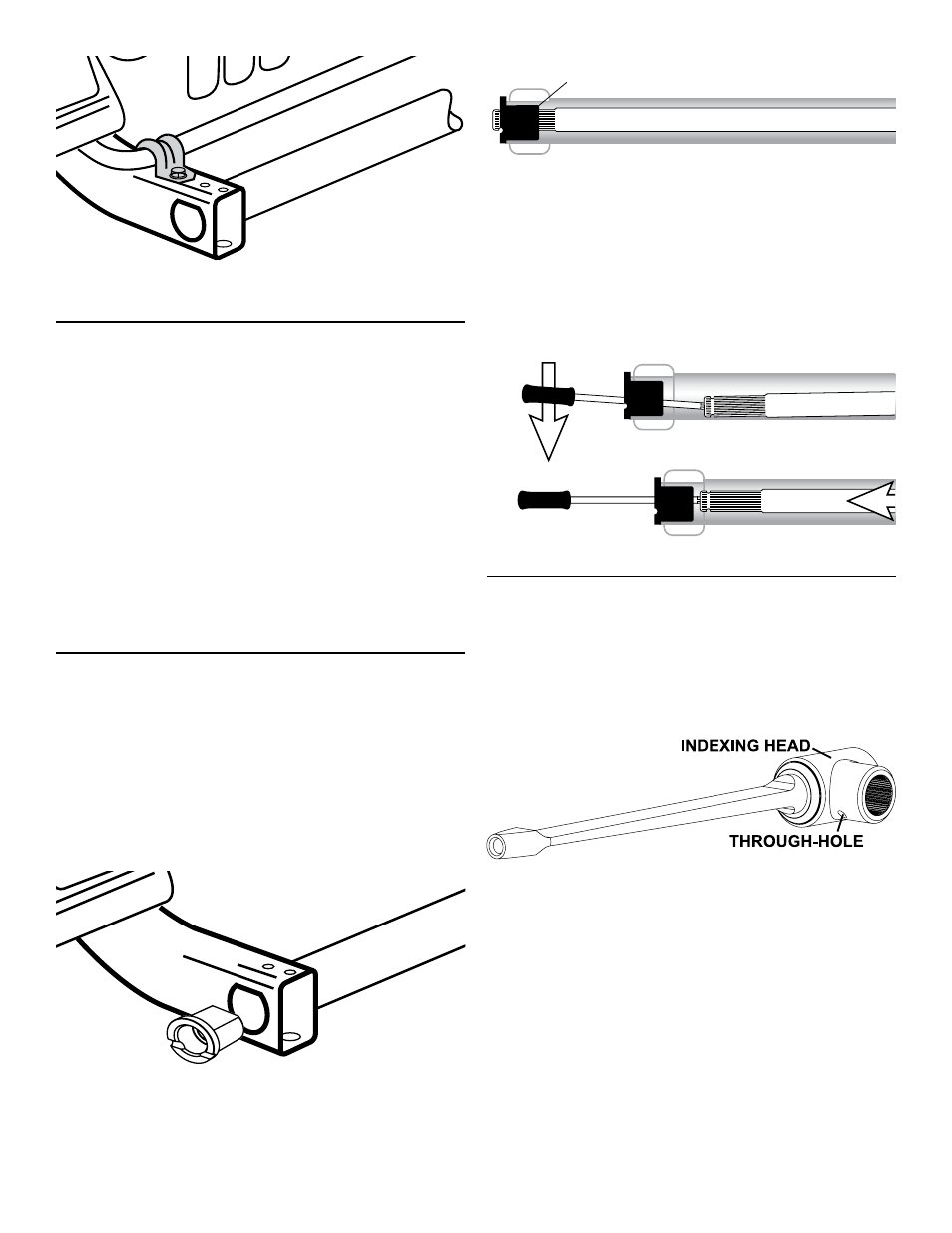
4. INSTALL TORSION BAR
Insert a Torsion Bar Bushing (D) into each end of
the tubular crossmember.
HINT: A block of wood
and soft mallet may be useful to fully seat bushing
into crossmember. Do not use brute force – only
light tapping with mallet. A light application of
silicone lubricant to outer surface of bushing may
also be used. If bushings are still difficult to insert,
contact JKS at 877-533-7557 for technical assis-
tance.
Wipe down the Torsion Bar (C) with a light applica-
tion of Silicone lubricant.
Install Torsion Bar (C) by guiding it through the
Torsion Bar Bushings (D) until it is centered.
CROSS MEMBER
CHASSIS
RAIL
BUSHING
TORSION BAR
HINT: To guide torsion bar through bushing at far end of
crossmember, insert a Philips head screwdriver through
bushing and into center hole of torsion bar as illustrated
below. Pry torsion bar up using screwdriver while pushing
it through the bushing from the opposite end.
Use caution to avoid damaging bushings when install-
ing torsion bar.
CROSS MEMBER
CHASSIS
RAIL
BUSHING
TORSION BAR
CROSS MEMBER
CHASSIS
RAIL
BUSHING
TORSION BAR
5. INSTALL BLADE ARmS
Locate the Blade Arm Assemblies (A & B) and
identify their correct mounting location by read-
ing the label applied to the Indexing Heads. “RH”
indicates Right-Hand side, and “LH” indicates Left-
Hand side.
Hint: When installed correctly, the 1/4”
through-hole will be on bottom of Indexing Head.
BLADE ARM ASSEMBLY
Slide the splined opening of the Indexing Head on
to end of Torsion Bar (C).
HINT: It may be neces-
sary to gently tap side of Indexing Head with a
rubber mallet to fully engage splines. Use a clean,
soft towel to protect the polished finish.
Slowly pivot the Blade Arm Assembly (A) up or
down until the 1/4” through-hole in Indexing Head
aligns with the access groove in the Torsion Bar
Bushing (D) as illustrated below.
Insert a 1/4" Dowel Pin (E) into the through-hole as
shown below.
Drive the 1/4” Dowel Pin (E) into through-hole until
it is centered as shown below.
HINT: A hammer