Parts, Attention installer, Installation – JKS 9100 User Manual
Page 2
JKS9100
JKS Switchblade Swaybar Installation
2 Page
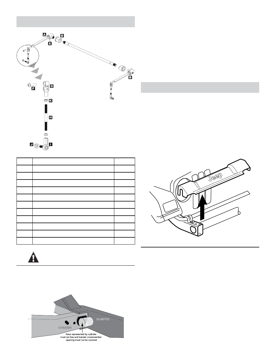
Parts
Description
QTY
A
Blade Arm Assembly (Left-Hand)
1
B
Blade Arm Assembly (Right-Hand)
1
C
Torsion Bar
1
D
Torsion Bar Bushing
2
E
1/4” Dowel Pin
2
F
1/2” x 1-3/4” Socket Head Cap Screw
2
G
Gimbal Joint Assembly
2
H
Connecting Rod
2
I
Rod End
2
J
1/2” Flanged Locking Nut
2
K
1/2” Jam Nut
4
ATTENTION INSTALLER
BEFORE YOU INSTALL THIS PRODUCT, verify the
front bumper and its mounting system do not interfere
with the D-shaped tubular crossmember openings or
surrounding area, as illustrated below.
If the bumper interferes with this product, it will be
necessary to clearance the bumper or mounting sys-
tem to allow fitment. Due to the number of possible
bumper configurations and other variables beyond
our control, we cannot provide instructions for this
procedure nor can we encourage it to be attempted.
If any bumper modifications are necessary to install
this product, it is the sole responsibility of the install-
er or vehicle owner to ensure the work is performed
properly and neither structural integrity nor safety
have been compromised.
Installation
1. REmOvE FRONT BUmPER
Disconnect any auxiliary driving/fog lamps mount-
ed to front bumper, if equipped.
Remove the mounting hardware that secures the
front bumper to the chassis.
Remove the front bumper assembly from the
vehicle.
Remove the front bumper valence from the chas-
sis.
2. REmOvE FRONT SWAYBAR
Remove the mounting hardware that secures the
front swaybar links to the swaybar and axle hous-
ing.
HINT: If difficult to remove, use special factory
removal tool PN MB991113 (Miller Special Tools,
800-801-5420) or similar tie rod end removal tool.
Remove swaybar links from vehicle.
Remove swaybar mounting bolts and bushing
retainers from chassis.