JKS OGS166 User Manual
Page 8
JKSOGS166
JKS Front Trackbar + Sector Shaft Reinforcement Installation
8 Page
On factory 6-cylinder engine applications, Frame
Bracket (P) should be located directly across from
driver-side mounting point.
On Hemi 8-cylinder engine applications, Frame
Bracket (P) should be located further toward rear
of vehicle to allow Chassis Connector Tube (O) to
clear the engine oil filter. Leave enough distance
between Connector Tube and filter to allow for
“engine torqueing”, and to accommodate oil filter
changes.
Photos in this document illustrate installation on
Hemi 8-cylinder application.
Make sure 1/2” x 5/8” Rod Ends (Q and R) do not
bottom out on either Trackbar Chassis Bracket (A)
or weld-on Frame Bracket (P).
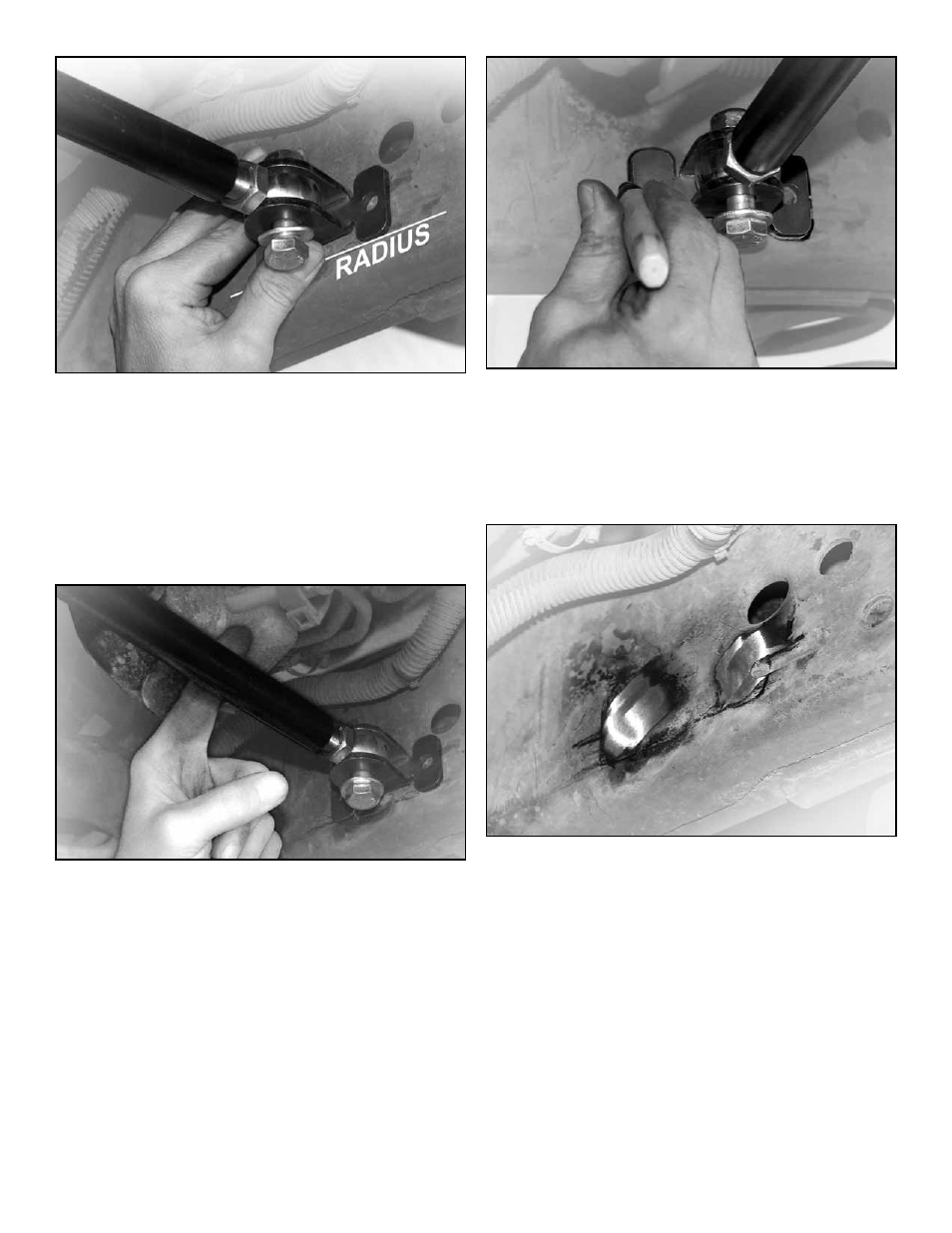
Twist the Chassis Connector Tube (O) to lengthen
the member until Frame Bracket (P) is pressed
firmly against desired mounting location on chas-
sis.
Transfer perimeter of mounting flanges and
location of plug weld holes onto chassis using a
marker or scribe.
Twist the Chassis Connector Tube (O) in opposite
direction to shorten the member and move the
Frame Bracket (P) out of position.
Remove any paint from area on chassis where lo-
cation of plug weld holes are marked.
HINT: A die
grinder with a sanding wheel is useful for removing
paint from chassis.
Reposition Frame Bracket (P) and lengthen the
Chassis Connector Tube (O) until weld-on bracket
is pressed firmly against desired mounting location
on chassis.
Tack weld Frame Bracket (P) to chassis rail.
Remove the 1/2” hardware that secures the Rod
End to Frame Bracket (P) and move the Chassis
Connector Tube (O) out of position for easier ac-
cess to plug weld holes.