Product: chassis brace connector, Installation – JKS OGS166 User Manual
Page 7
JKSOGS166
JKS Front Trackbar + Sector Shaft Reinforcement Installation
Page 7
Allow welded area to cool. Then apply black spray
paint to Frame Mount (I) and any bare metal to
protect the surfaces from corrosion.
4. INSTALL STEERING SECTOR PILLOW
BLOCK
Apply a small amount of anti-seize lubricant to
threads of two 3/8” x 1” Bolts (L) and 1/2” x 2” Bolt
(U).
Slide Steering Sector Pillow Block (E) onto Sec-
tor Bearing Nut (G) and loosely install the two 3/8”
Bolts (L) and 1/2” Bolt (U). Do not tighten bolts yet.
Next insert the 7/16” x 1-3/4” Bolt (J) with 7/16”
Split Washer (K) into hole in Pillow Block. Thread
the 7/16” Bolt into Pillow Block Frame Mount (I) by
hand, but do not tighten yet.
Starting with the two 3/8” Bolts (L), slowly and
evenly tighten all four mounting bolts until snug. Do
not fully tighten any of the four mounting bolts yet.
Product:
Chassis Brace Connector
Installation
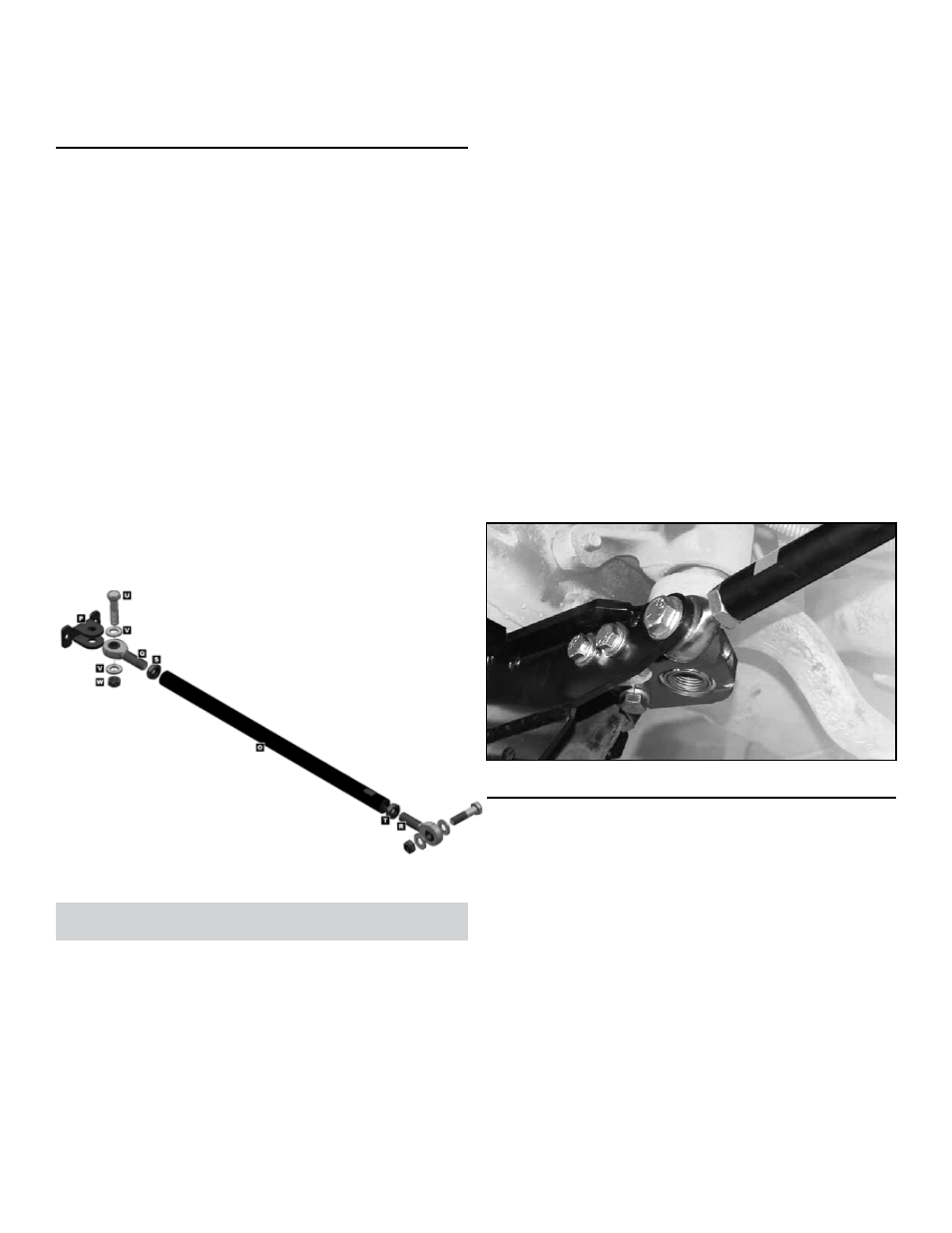
5. MOUNT CONNECTOR TO CHASSIS
BRACKET
Assemble Chassis Brace Connector by completely
threading a 5/8” Jam Nut (S and T) onto each 1/2”
x 5/8” Rod End (Q and R), and then inserting a rod
end into each end of the Chassis Connector Tube
(O). Leave approximately 1/2” of thread showing
between ends of tube and jam nuts.
Remove the 1/2” x 2” Bolt (U) from the Steering
Sector Pillow Block (E). Then loosen both 3/8” x 1”
Bolts (L) and the 7/16” Bolt (J) just enough to allow
the Rod End (Q or R) to be inserted between the
Chassis Bracket and Pillow Block.
Locate the slotted end of the Chassis Connector
Tube (O) and slide the rod end closest to it be-
tween the Chassis Bracket and Pillow Block. Re-
insert the 1/2” x 2” Bolt (U) and finger tighten.
Starting with the two 3/8” Bolts (L), slowly and
evenly tighten all four mounting bolts until snug. Do
not tighten only one bolt at a time – all bolts should
be tightened together.
Using a torque wrench, continue to tighten the two
3/8” Bolts (L) to 35 ft-lbs., and tighten the 7/16”
Bolt (J) to 50 ft-lbs. Do not fully tighten the 1/2”
Bolt (U) until specified later in these instructions.
HINT: The extra 1/2” Locking Nut (W) & 1/2” Flat
Washer (V) supplied with Front Trackbar Chassis
Brace are not used when mounting to Steering
Sector Pillow Block (E).
6. MOUNT CONNECTOR TO
PASSENGER-SIDE CHASSIS RAIL
On opposite end of Chassis Connector Tube (O),
install weld-on Frame Bracket (P) using a 1/2” x 2”
Bolt (U), two 1/2” Flat Washers (V) and 1/2” Lock-
ing Nut (W). Tighten hardware until snug.
Position Frame Bracket (P) on passenger-side
chassis rail with bottom of mounting flange located
just above radius on chassis.