Fabric device management interface, Advanced switch properties, Figure 31 advanced switch properties dialog – HP McDATA 4Gb SAN Switch for HP BladeSystem p-Class User Manual
Page 72: 31 advanced switch properties dialog
72
Fabric Device Management Interface
Fabric Device Management Interface (FDMI) provides a means to gather and display device information
from the fabric, and allows FDMI capable devices to register certain information with the fabric, if FDMI is
enabled. McDATA Web Server or Element Manager will report any and all FDMI information reported by
the entry switch, if FDMI is enabled on the entry switch. To view FDMI data, FDMI must be enabled on the
entry switch and on all other switches in the fabric that are to report FDMI data.
FDMI is comprised of the fabric-to-device interface and the application-to-fabric interface. The
fabric-to-device interface enables a device’s management information to be registered. The
application-to-fabric interface provides the framework by which an application obtains device information
from the fabric. Use the
FDMI HBA Entry Limit field on the Switch Properties dialog to configure the
maximum number of HBAs that can be registered with a switch. If the number of HBAs exceeds the
maximum number, the FDMI information for those HBAs can not be registered.
Use the
FDMI Enabled option on the Switch Properties dialog to enable or disable FDMI. If FDMI is
enabled on an HBA, the HBA forwards information about itself to the switch when the HBA logs into the
switch. If FDMI is enabled on a switch, the switch stores the HBA information in its FDMI database.
Disabling FDMI on a switch clears the FDMI database. If you disable FDMI on a switch, then re-enable it,
you must reset the ports to cause the HBAs to log in again, and thus forward HBA information to the switch.
Click the
Devices data window tab and click (i) in the Details column of the Devices data window to view
detailed FDMI information for a device. The Detailed Devices Display dialog displays the specific
information for that device. See ”
” on page 34 for more information.
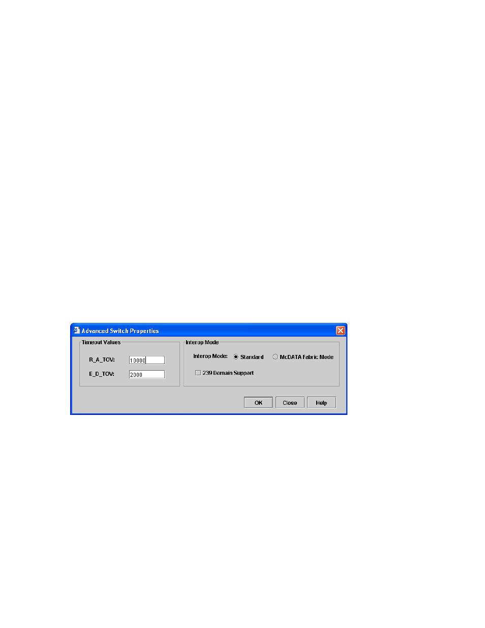
Advanced switch properties
The Advanced Switch Properties dialog shown in
enables you to set the timeout values and
interop mode settings. The Advanced Switch Properties dialog is available for only the entry switch,
because an in-band switch can not be taken offline. The switch will automatically be taken offline
temporarily and will be restored to its original state after the changes are completed. Select
Switch >
Advanced Switch Properties to open the Advanced Switch Properties dialog. Click OK after making any
changes to put the new values into effect. The default interop mode is Standard.
Figure 31
Advanced switch properties dialog
Use the Advanced Switch Properties dialog to change the following switch configuration parameters: