Program port connections and wiring – AMX NetLinx Master-Ethernet Card/Module NXC-ME260 User Manual
Page 15
Installation and Wiring
9
NXC-ME260 NetLinx Master-Ethernet Card/Module
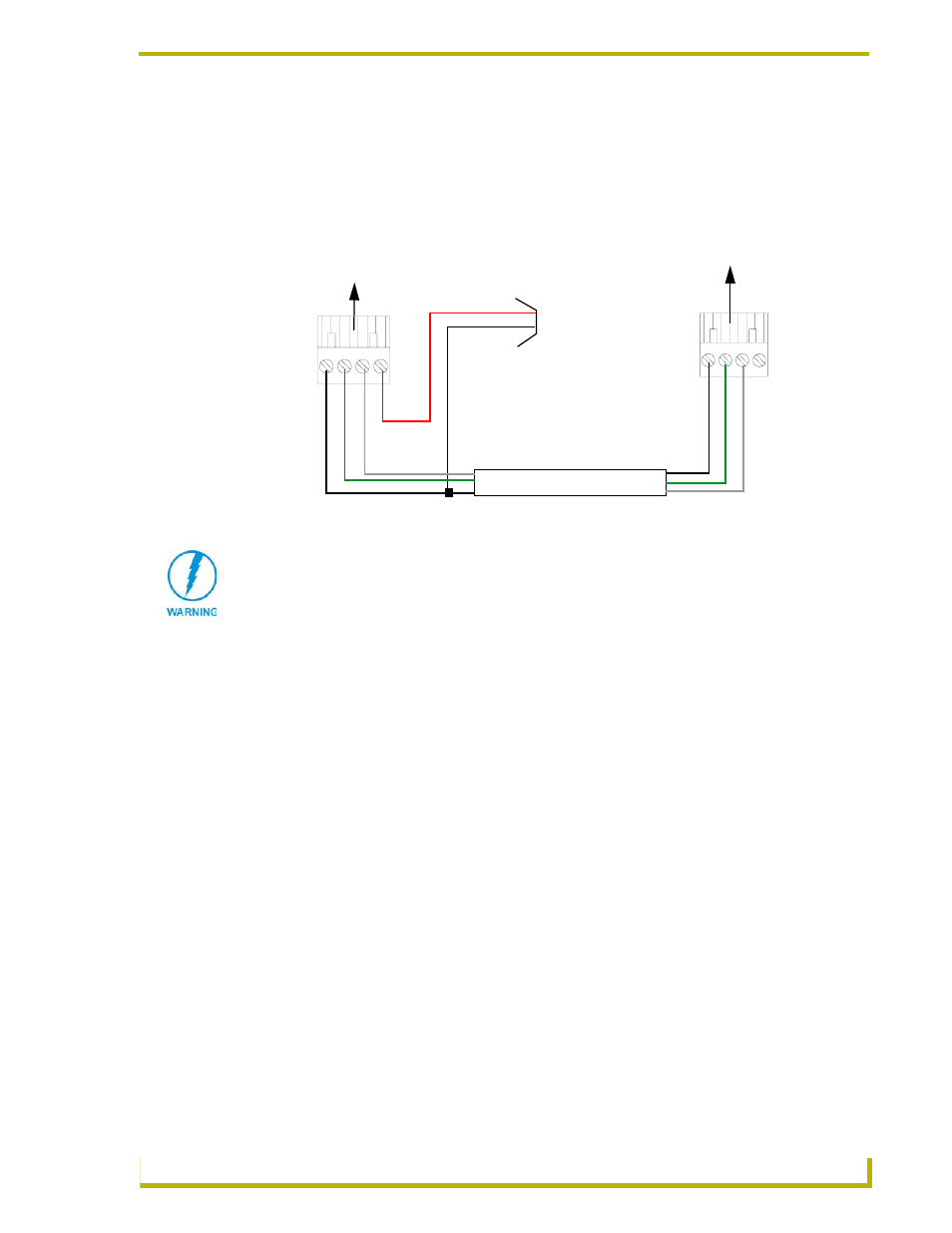
Using the 4-pin mini-Phoenix connector for data with external power
To use the NetLinx 4-pin 3.5 mm mini-Phoenix (female) captive-wire connector for data
communication and power transfer; the incoming PWR and GND cable from the PSN must be
connected to the AXlink cable connector going to the NXC-ME260. FIG. 7 shows the wiring
diagram. Always use a local power supply to power the Master card.
Make sure to connect only the GND wire on the AXlink/PWR connector when using a separate
12 VDC power supply. Do not connect the PWR wire to the AXlink connector’s PWR (+) opening.
Program Port Connections and Wiring
The NXC-ME260 is equipped with two Program ports. One is located on the front panel and the
other is on the rear for easy access. The port on the front panel is an RS232 (male) connector and
the rear port is a grey 5-pin (male) connector.
Use a Programming cable to connect the Program port to your PC's COM port to communicate with
the Master card. Then, you can download NetLinx programs to the Master card using the NetLinx
Studio 2.1 software program. Refer to the NetLinx Studio instruction manual for programming
instructions.
FIG. 7 4-pin mini-Phoenix connector wiring diagram (using external power source)
PWR (+)
GND (-)
Local +12 VDC
(coming from
To the ME260
To the external NetLinx device
AXlinx/PWR connector
power supply
the PSN
power supply)
Top view
Top view
AXP/
TX
AX
M/RX
GND -
AXP
/TX
AX
M
/R
X
GND -
When connecting an external power supply, do not connect the wire from the PWR
terminal (coming from the external device) to the PWR terminal on the Phoenix
connector attached to the NXC-ME260. Make sure to connect only the AXM, AXP,
and GND wires to the Master’s Phoenix connector when using an external PSN
power supply.