Setting the program port dip switch – AMX NetLinx Master-Ethernet Card/Module NXC-ME260 User Manual
Page 12
Installation and Wiring
6
NXC-ME260 NetLinx Master-Ethernet Card/Module
PRD mode prevents the NetLinx program stored in the Master from running when you power up
the NXC-ME260. PRD mode should only be used when you suspect the resident NetLinx program
is causing inadvertent communication and/or control problems. If necessary, place the Master in
PRD mode and use the NetLinx Studio 2.1 program to resolve the communication and/or control
problems with the resident NetLinx program. Then, download the new NetLinx program and try
again.
Setting the Program Port DIP switch
It is recommended that the baud rate DIP switch be set prior to any installation of the NXC-ME260
card.
1.
Locate the red baud rate DIP switch (FIG. 4).
2.
Set DIP switch positions according to the information listed in the Baud Rate Settings and
PRD Mode Settings tables above.
3.
Follow the procedures outlined in the NXC-ME260 Installation and Mounting
Procedures section on page 15.
If the card has already been installed:
1.
Disconnect the power supply from the 2-pin PWR (green) connector on the Master Card.
2.
Unsecure the NXC-ME260 by unscrewing the two faceplate securing screws (on both sides of
the faceplate) using a Phillips-head screwdriver (FIG. 4).
3.
Carefully slide-out the card and locate the red baud rate DIP switch (FIG. 4).
4.
Set the DIP switch positions according to the information listed in the Baud Rate Settings and
PRD Mode Settings tables (page 5).
5.
Place the Master card back into its’ housing and resecure the two faceplate securing screws.
6.
Reconnect the 12 VDC power supply to the 2-pin PWR connector and apply power.
Think of the PRD Mode (On) equating to a PC’s SAFE Mode setting. This mode
allows a user to continue powering a unit, update the firmware, and download a new
program while circumventing any problems with a currently downloaded program.
Power must be cycled to the unit after activating/deactivating this mode on the rear
Program Port DIP switch #1.
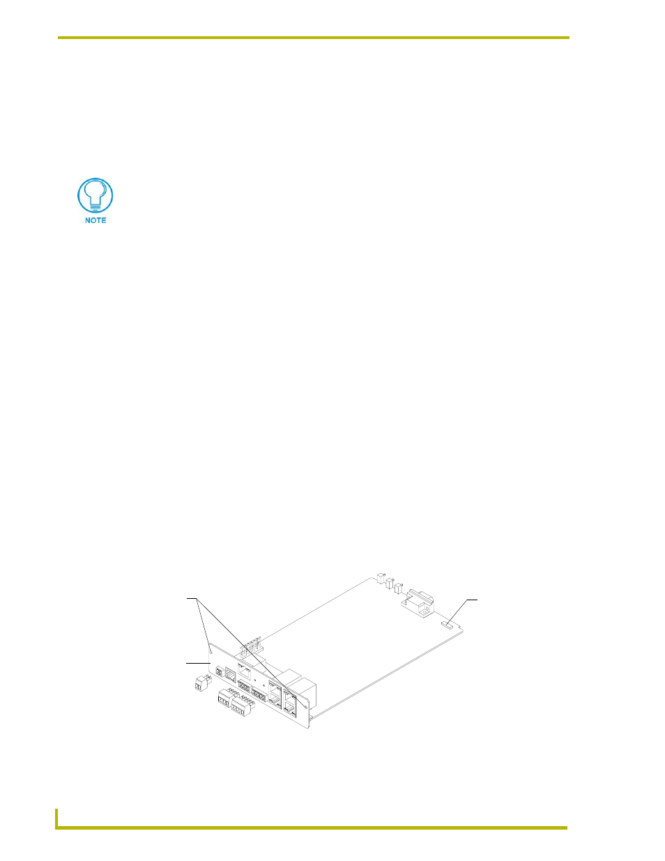
FIG. 4 Component locations on the NXC-ME260
Baud rate DIP
switch for the
Program port
Faceplate
securing
screws (2)
Faceplate
(red)