Figure 3-6 – Agilent Technologies E8247C PSG CW User Manual
Page 82
72
Chapter 3
Optimizing Performance
Creating and Applying User Flatness Correction
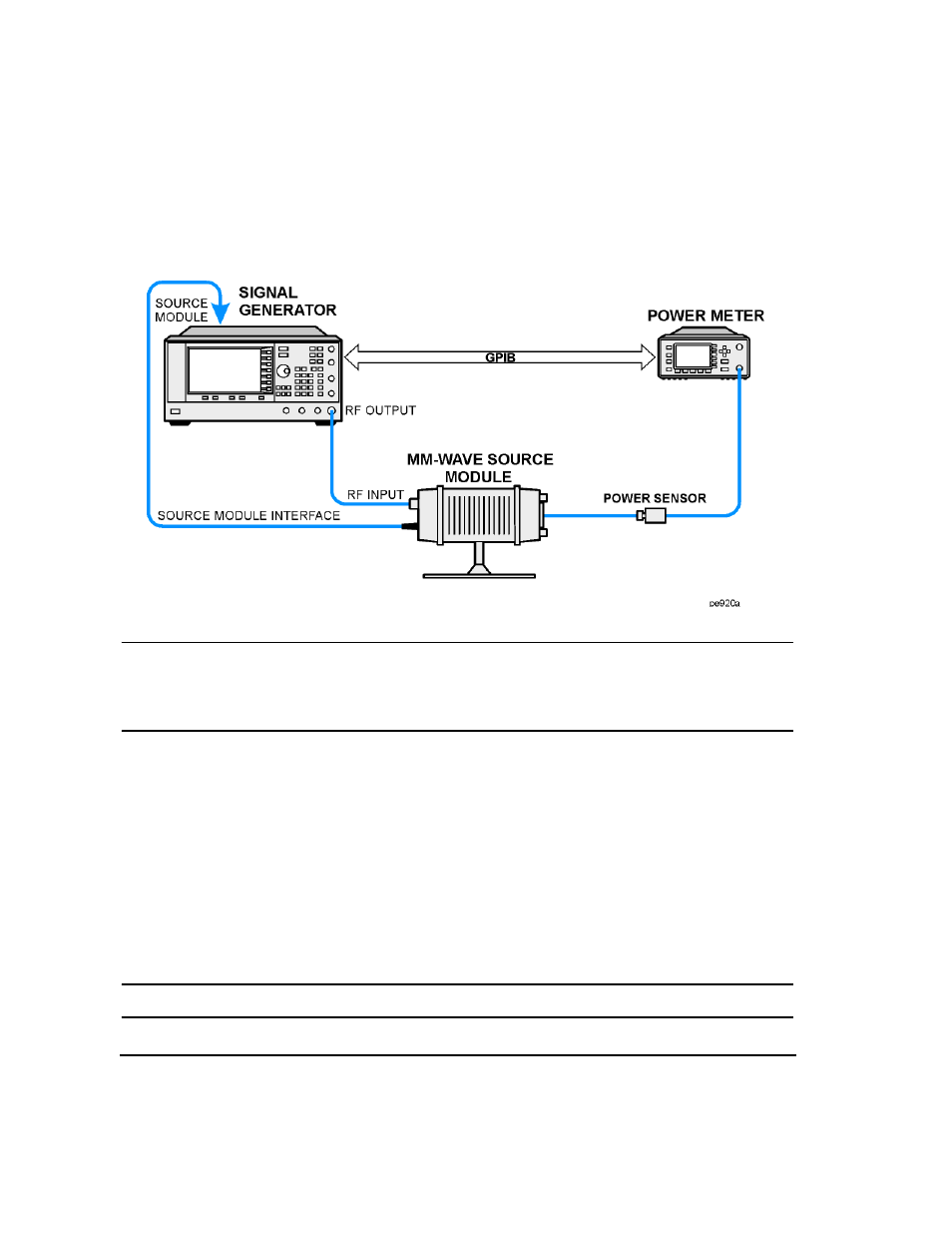
Figure 3-6
User Flatness with mm-Wave Source Module and Option 1EA Signal Generator
NOTE
To ensure adequate RF amplitude at the mm-wave source module RF input when using
Option 1EA signal generators, maximum amplitude loss through the adapters and cables
connected between the signal generator’s RF output and the mm-wave source module’s RF
input should be less than 1.5 dB.
Configure the Signal Generator
1. Turn on the signal generator’s line power. At power-up, the signal generator automatically does the
following:
•
senses the mm-wave source module
•
switches the signal generator’s leveling mode to external/source module
•
sets the mm-wave source module frequency and amplitude to the source module’s preset values
•
displays the RF output frequency and amplitude available at the mm-wave source module output
The
MMMOD
indicator in the
FREQUENCY
area and the
MM
indicator in the
AMPLITUDE
area of the signal
generator’s display indicate that the mm-wave source module is active
NOTE
For specific frequency/amplitude ranges, see the mm-wave source module specifications.