Connector & wiring diagram, 4 connector & wiring diagram – FUTEK IPM650 Series User Manual
Page 8
EM1004-B
- 8 -
10 Thomas, Irvine, CA 92618 USA
Tel: (949) 465-0900
Fax: (949) 465-0905
Toll Free: (800) 23 FUTEK
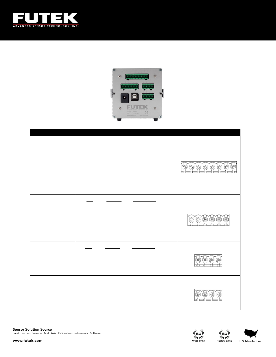
4 Connector & Wiring Diagram
Connectors
Description
Diagram
Amplified Input
Pin
Symbol
Description
1
G
Ground
2
G
Ground
3
24V OUT
24VDC Output
4
5V OUT
5VDC Output
5
-V
-V from sensor
6
+V
+V from sensor
7
PLEAD
n/a
8
PLAG
n/a
1
2
3
4
5
6
7
8
Strain Gauge
Input
Pin
Symbol
Description
1
G
Ground
2
TEDS
TEDS Data
3
-S
-Signal
4
+S
+Signal
5
-E
-Excitation
6
+E
+Excitation
1
2
3
4
5
6
Relays
Pin
Symbol
Description
1
-R2
Solid state relay 2
2
+R2
Solid state relay 2
3
-R1
Solid state relay 1
4
+R1
Solid state relay 1
1
2
3
4
Analog Output
Pin
Symbol
Description
1
-VOUT
Voltage output (-)
2
+VOUT
Voltage output (-)
3
G
Ground (current)
4
IOUT
Current output
1
2
3
4