Alarm functions – Metex 8760CLP Total Free Chlorine & pH Analyzer User Manual
Page 50
AQUAMETRIX INC.
1-800-742-1413 www.aquametrix.com
50
ALARM FUNCTIONS
Two alarms, alarm A and alarm B, are a standard feature. Each alarm has an alarm contact associated
with it which can be used for remote alarm indication or for control functions. The two alarms function
independently of each other. Either alarm can
independently monitor any of the inputs.
Each alarm features an adjustable set-point, user-
selectable alarm type, and adjustable differential (also
called hysteresis). The alarm types which are
available are “no chlorine”, high, low, deviation, and
fault. Alarms can be set anywhere between 0 ppm
and 2 ppm for HOCl, 0 ppm to 5 ppm for tFCl, 0 pH
to 14 pH for pH and -5 °C to 105 °C for temperature.
Use of Relay Contacts
By default, the relay contacts will be used to indicate
alarm conditions. Alarm conditions are indicated
using both the LED and the relay contact. This usage
of the relay contacts is selected by setting [CONF]
[AL] [AL.A] [FUNC] and [CONF] [AL] [AL.b]
[FUNC] to [AL]. If some other use is selected for the
relay contacts then the alarm cannot simultaneously
use the contact; however, the alarm function
continues using the LED, display messages and serial
communication.
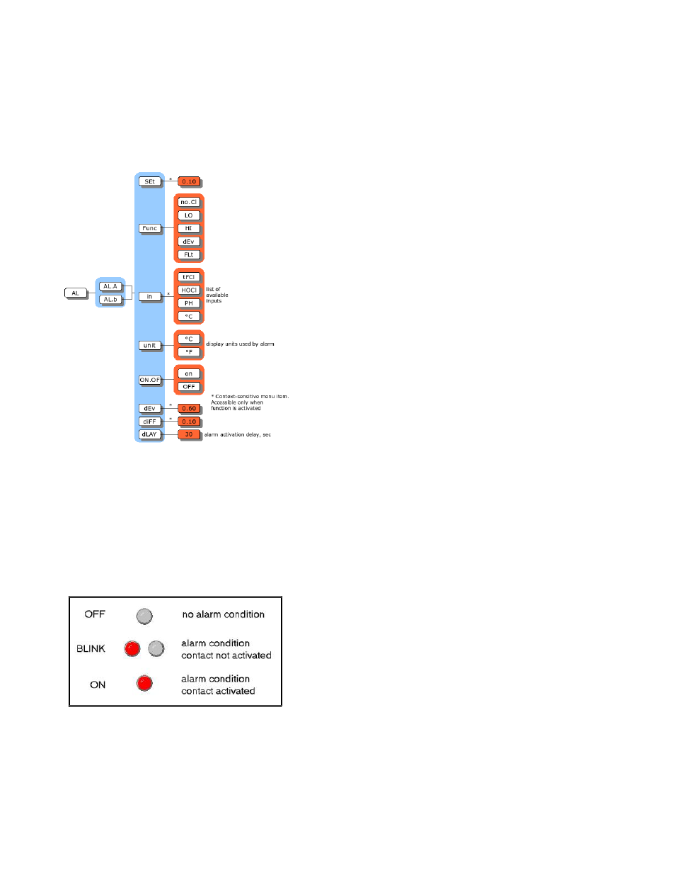
Alarm Indication
The A and B LEDs on the front panel show the current state of each alarm and alarm contact. In
addition, an alarm condition for an input will cause the sample display for that input to alternate with the
alarm function, [no.Cl], [LO], [HI], [dEv], or [FLt]. An LED that is blinking or on shows that the alarm
has an alarm condition. The status of the alarm contact can also be determined at a glance; the
corresponding alarm contact is activated when the LED is on and is deactivated while the LED is
blinking or off. Note that the alarm LED will blink while the alarm is in MANUAL because this also
deactivates the alarm contacts.
Each alarm will generate a caution number in the error
menu. Refer to Caution Messages for Alarms in the
Error Messages section for the meaning of each alarm
caution. The alarm cautions will not cause the error
LED to come on because the error LED only comes on
if there are any errors. To view alarm caution(s) using
the error menu, select [Err] from the main menu, then
use the Up or Down arrow key to scroll through the list
of errors and cautions, if any.
Each alarm situation also causes an event tag to be
written into an internal log which can be accessed using the IC Net Intelligent Access Program. The
IC Net program uses the analyzer's serial communication port to read and display this information.
Illustration 39
: Alarm status indication, alarm LEDs
Illustration 38: Alarm menu