Assembly of the chlorine sensor – Metex 8760CLP Total Free Chlorine & pH Analyzer User Manual
Page 25
AQUAMETRIX INC.
1-800-742-1413 www.aquametrix.com
25
Assembly of the Chlorine Sensor
This procedure should be done over a sink. Protective eye-wear and plastic or rubber gloves are
recommended when handling the electrolyte, a salt solution. Wash hands with water if the electrolyte
comes in contact with the skin.
1. Galvanic chlorine sensors should have a current drain at all times. Assemble sensor while powered
to analyzer OR with a short; coax center to shield. The chlorine sensor has a 5-pin DIN connector
and the sensor is shipped with a shorting strap across two pins (refer to illustration 8). Remove this
shorting strap prior to connecting to analyzer. Note the location of the pins requiring short for future
sensor storage.
2. Disassemble the chlorine sensor by removing the CPVC membrane retainer (see illustration 20) at
the sensor tip. Pull straight down on the retainer. The retainer holds the membrane in place and
removing the retainer will release the fill solution and expose the silver coils and gold sensing tip.
The fill solution is not hazardous so if any gets on the skin simply rinse with water.
3. Discard the used membrane and rinse the retainer and fill solution cavity thoroughly with deionized
water.
4. Replace the membrane using one of the following procedures:
A. Assembly with Membrane Replacement
Toolkit
Required Materials
i. P/N AM-A2104035 Membrane replacement toolkit
ii. P/N AM-A2104036 Membrane kit
iii. P/N AM-A1100239 Chlorine sensor fill solution
Membrane Replacement Procedure
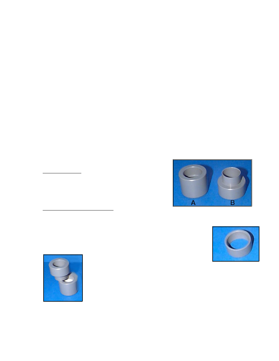
a) The membrane replacement toolkit, P/N AM-A2104035, consists of two
pieces which fit together into one unit; separate the toolkit into it's
individual components (refer to illustration 19). One piece will be a
cylindrical shape (A) and the other will resemble a "T" (B).
b) Place the membrane retainer, tapered side up, into the larger diameter hole
of the cylindrical component of the membrane
replacement toolkit.
c) Place one membrane from P/N AM-A2104036,
shiny side up, over the membrane retainer.
d) Place the narrow end of the second component
from the membrane toolkit onto the membrane containing component (refer
to illustration 21). Press firmly on top of the second component until the
two components fit together securely.
Illustration 20: Membrane
retainer
Illustration 21:Step d) of
membrane replacement
procedure
Illustration 19: Membrane toolkit