Output signals – Metex 8760CLP Total Free Chlorine & pH Analyzer User Manual
Page 49
AQUAMETRIX INC.
1-800-742-1413 www.aquametrix.com
49
OUTPUT SIGNALS
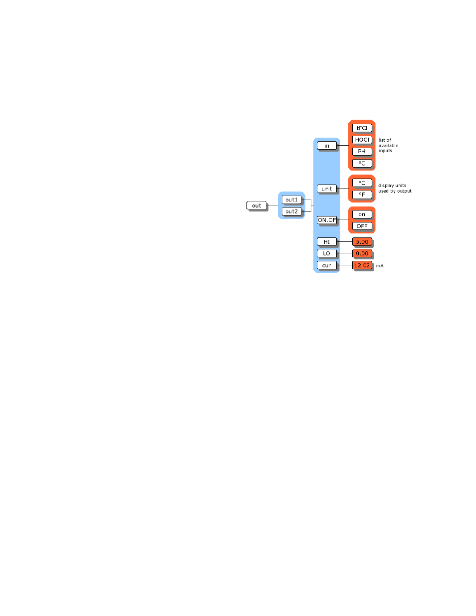
Two assignable 4 mA to 20 mA output channels are provided. The user may configure the analyzer to
determine which input signal will be transmitted by each 4 mA to 20 mA output channel. Each output
channel can be independently configured to
transmit a chlorine, pH or temperature signal.
The output channels function independent of
each other. Each output channel has a
separate on/off switch and adjustable low and
high span (or scale) adjustments. This makes
it possible, for example, to transmit both
HOCl and tFCl signals, each using separate
high and low adjustments.
To adjust the output span or output window
for chlorine, pH or temperature signals, set
[LO] to correspond to the low end of the scale
or 4 mA output, and set [HI] to correspond to
the high end of the scale or 20 mA output.
The analyzer will automatically scale the
output according to the new settings.
Reversing the 4 mA to 20 mA Output
The low scale setting will normally be lower than the high scale setting. It is possible to reverse the
output or "flip the window" by reversing the settings of the low and high scale.
Simulated 4 mA to 20 mA Output
Select [cur] from the menu to display the output current in mA that is presently being transmitted. The
display will be updated as the output signal changes based on the input signal and the program settings.
From here, one can watch the output respond to the change in the input signal. This is useful for
verifying program settings and for testing the hardware calibration.
In addition, the 8760CLP output can be used to calibrate downstream receivers such as 4 mA to 20 mA
recorders or data acquisition systems. To simulate a different 4 mA to 20 mA output signal press
ENTER to access edit mode. Edit the displayed mA value to display the desired output needed for
testing the output signal. Press ENTER to select the displayed value. The output signal will be adjusted
to put out the desired current. This process can be repeated as often as necessary.
The output signal is held at the displayed level until the program leaves this part of the menu.
Units for Outputs
The output menu will be using different units for its settings, depending on the input selected. Select
[unit] from the output menu to display the units in use for this output.
Illustration 37: Output menu