Cos( ), F( ), U t ( ) – GW Instek GRF-1300A User Manual
Page 99: U t ( ) cos, U t v t, Rf communication and signals experiments
RF Communication and Signals Experiments
modulated signal constant, only to increase (up-conversion) o
decrease (down conversion) the carrier frequency. From the
spectrum point of view, the essence of mixing is to linearly mov
the spectrum of the modulated signal along the frequency ax
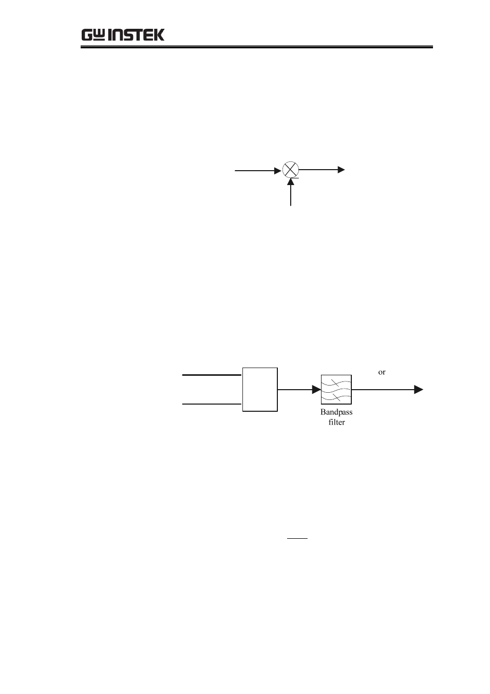
Therefore, a mixer circuit must be composed of a non-linear
device with a mult
r
e
is.
iplicative function as well as band-pass filters,
as shown in 10-1.
Figure 10-1 Th
c
f
L
f
I
f
e
mixer circuit
er
The mixer multiplies the modulated signal
with carri
frequency
c
( )
s
u t
f
and the local oscillator signal
( )
L
u t
with the
oscillation frequency
L
f
, as shown in figure 10-2. According to t
multiplication of trigonometric functions, the multi licatio
in th
and diff ence of
c
he
p
n of
the inputs r ults
addition
e
es
e
r
f
and
L
f
.I.e.,
I
L
C
f
f
f
=
+
and
|
|
I
L
C
f
f
f
−
=
, where
I
f
is called the
intermediate frequency. The mixing frequency signal with the
carrier frequency
I
f
is called the intermediate frequency signal
( )
.
i
u t
Figure 10-2
Mixer sign
c
f
L
f
( )
s
u t
( )
L
u t
x
y
xy
L
C
f
f
+
|
|
L
C
f
f
−
|
|
L
C
f
f
±
al
diagram
t sig
is
Say the modulated inpu
nal
)
( )
s
u t
( )
cos(
s
s
c
u t
V
t
ω
=
cos(
)
L
L
L
V
t
,
th
local oscillation sig
e
nal
is
( )
L
u t
( )
u t
ω
=
,
then the
product becomes
( )
cos(
) cos(
)
[cos(
)
cos(
) ]
2
S L
I
S L
c
L
c
L
L
c
V V
u t
V V
t
t
t
t
ω
ω
ω ω
ω ω
=
=
+
+
−
Passing through a band-pass filter and removing one of th
frequency components (
c
L
e
ω ω
+
or
L
c
ω ω
−
) completes the
frequency conversion.
the new carrier frequency is
the calculated result above is shown in the
Generally
called the IF signal.
The spectrum of
97