GW Instek GRF-1300A User Manual
Page 105
RF Communication and Signals Experiments
table 10-1.
Step5
5. Adjust the frequency of the RF output in the RF Synthesizer/FM
module. Observe the changes on the spectrum analyzer and
record it in table 10-1.
Step6
6. Adjust the frequency of the RF output in the RF Synthesizer/FM
module. Observe the changes on the spectrum analyzer and
record it in table 10-1.
Step7
7. Obtain the spectrum and amplitude of each spectral line
according to the previous step, calculate the conversion gain of
the down-converted product and calculate the isolation degree in
the IF In port. Record the experimental results in the table 10-2.
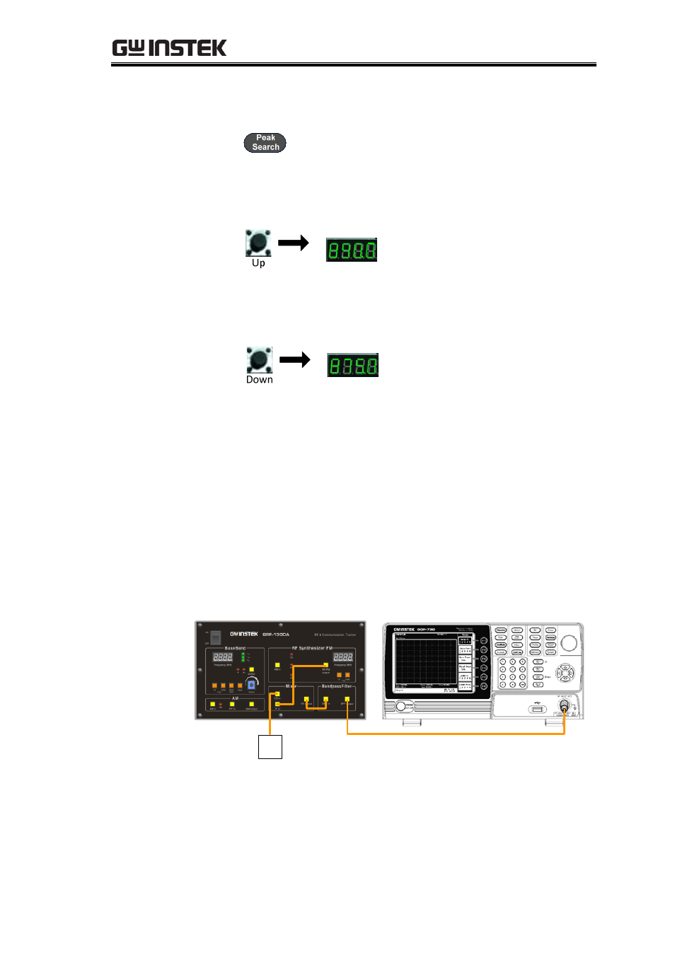
8. After completion of the above experimental steps, adjust the RF
frequency in the RF Synthesizer / FM module to 880MHz. Then,
connect the RF output port in the Mixer module to the BPF in port
in the Band Pass Filter module with the RF cable. Connect the RF
cable that was originally connected to the RF output port in the
Mixer module to BPF output port and keep the other connected to
the input port of the spectrum analyzer.
USG
9. Spectrum analyzer settings remain unchanged.
10.
Observe what changes on the spectrum analyzer and record
in table 10-3.
103