Grf-1300a user manual and teaching materials – GW Instek GRF-1300A User Manual
Page 40
GRF-1300A User Manual and Teaching Materials
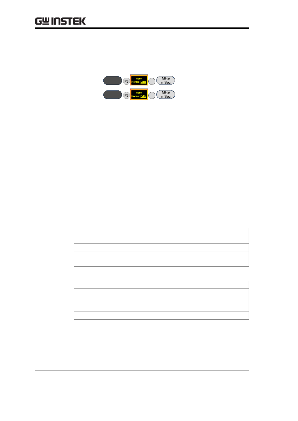
After step 6 is done, make sure the "Delta" marker is used
for the next steps and not the "Normal" marker. Set the Delta
Marker to the peak point of each harmonic and make a record
by drawing a simple sketch of the spectrum in table 2-1.
Step7
Marker
1
Step8
Marker
2
6.A function signal generator can also be used as a signal source
in the above measurement, but be aware that the amplitude of
the output signal can’t be too high.
dBm is a power unit that is referenced to 1mW. The
formula for X dBm = 10*log(Px/1mW)
Putting 10 mW into the above formula, we get 10 * log
(10/1) = 10 * 1 = 10dBm. Similarly if we input 100 mW into the
above formula, X = 10 * log (100mW/1mW) = 10 * 2 = 20dBm.
Because the output voltage of a signal generator is often
used expressed as a voltage into a 50 ohm load, you must
convert voltage to power. A few common values are listed
below:
Converting Voltage to dBm: (into 50 ohm load)
Vpp (V)
Vm (V)
Vrms (V)
P (mW)
dBm
10.00 5.00 3.54 250.00 23.98
5.00 2.50 1.77 62.50 17.96
2.00 1.00 0.71 10.00 10.00
1.00 0.50 0.35 2.50 3.98
Converting dBm to Voltage: (into 50 ohm load)
dBm
P (mW)
Vrms (V)
Vm (V)
Vpp (V)
20.00
100.00
2.24
3.16
6.32
10.00
10.00
0.71
1.00
2.00
0.00
1.00
0.22
0.32
0.63
-10.00
0.10
0.07
0.10
0.20
If voltage is measured without a load on an oscilloscope, the
Vpp and Vm values should be multiplied by 2. For instance,
when we get a measured value of 4Vpp into no load, it is the
equivalent of 2Vpp into 50 ohms, or 10dBm after conversion.
Experiment
results
38