Grf-1300a user manual and teaching materials – GW Instek GRF-1300A User Manual
Page 28
GRF-1300A User Manual and Teaching Materials
Figure B-3.
Basic structure of
a resolution
bandwidth filter
Mixers
Attenuators
Tunable LOs
RF Input
Detection
& Display
Unit
BPFs
RBW
Filter
IF
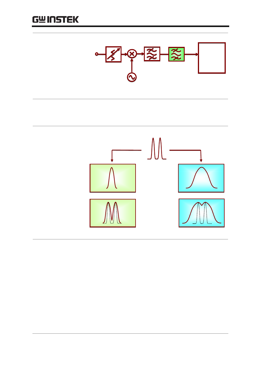
Figure B-4 shows how two different RBW filters distinguish
between two signals that are close to each other in frequency.
The bandwidth of RBW2 is wider that of RBW1.
Figure B-4.
The effect of
different RBWs
(1)
Signal under test
RBW
Results
RBW2
RBW1
After passing the narrower RBW1 filter, the components of
the two tone signal are clearly distinguished from each other as
a result. But in the wider RBW2 filter, the result is not as clear as
RBW1. We can predict that if the resolution bandwidth of RBW2
is wider, we could even misinterpret the result as only one
signal. This will also happen if these two signals are even closer
together in frequency.
Another case is when the amplitude of one signal is much
higher than the other; the smaller signal can still be detected
using RBW1, but it is obscured if RBW2 is used. Figure B-5
illustrates this difference. This is why these filters are known as
resolution bandwidth filters.
26