Grf-1300a user manual and teaching materials – GW Instek GRF-1300A User Manual
Page 66
GRF-1300A User Manual and Teaching Materials
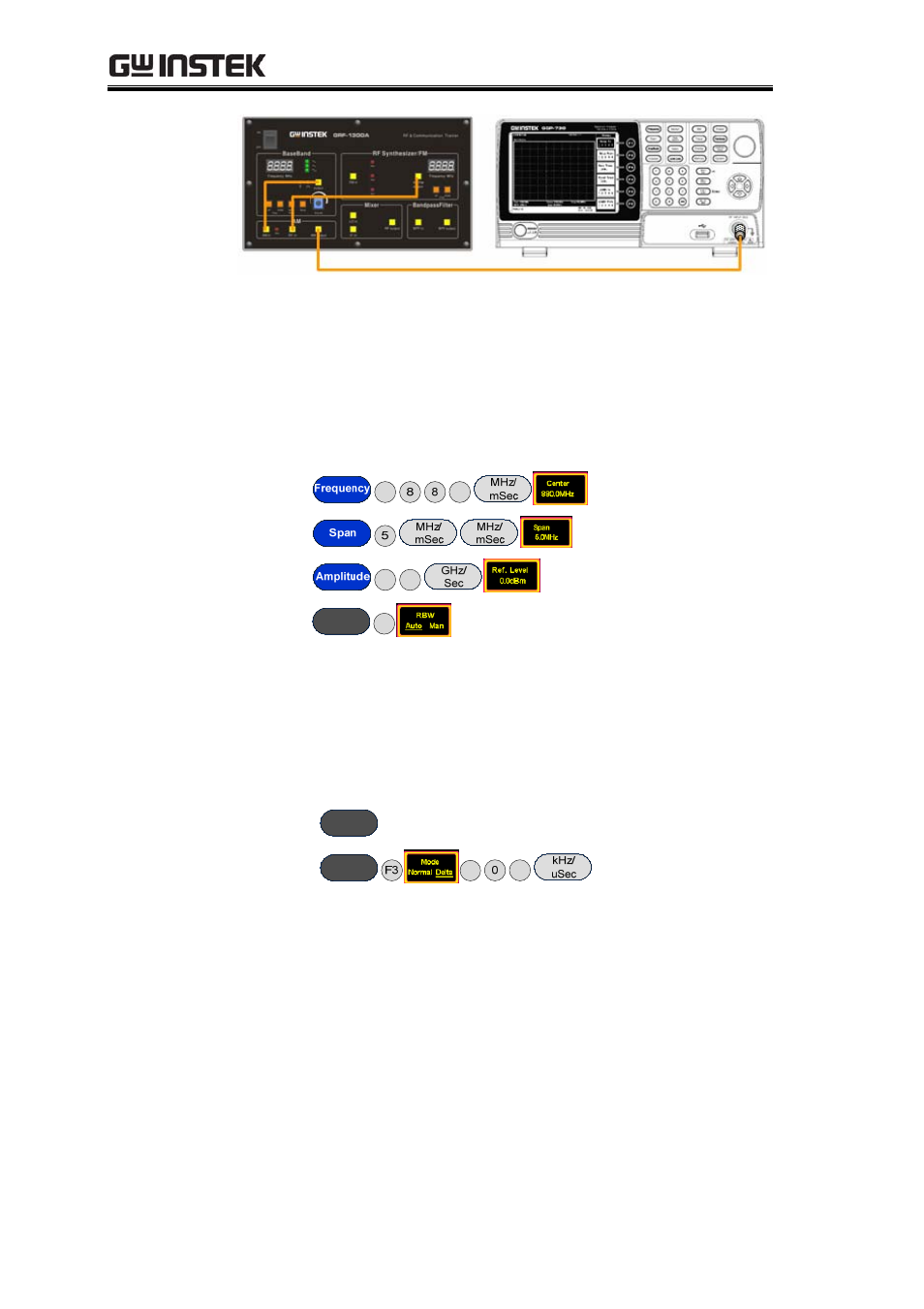
4. Set up the GSP-730 as follows:
• Center frequency:880MHz
• Span: 5MHz
• Reference level: 0dBm
• RBW: Auto
Step1
F1
0
Step2
Step3
F1
0
Step4
BW
F1
5. Use the Marker function to measure the carrier component of
the AM wave on the spectrum analyzer and the power of the
upper and lower sidebands. Use the oscilloscope to measure the
voltage at TP4 in relation to the position of the potentiometer
(i.e., the modulating amplitude). Draw the spectrum diagram in
Table 5-4.
Step5
Peak
Search
Step6
Marker
0
1
6. Turn the potentiometer counterclockwise to the half-way
mark. Measure the voltage with the oscilloscope. By changing
the output amplitude of the modulating signal, can you observe
any change in the spectrum? Record the experiment in Table 5-4.
7. Turn the potentiometer counterclockwise to decrease the
output voltage. Measure the voltage with the oscilloscope.
Observe any changes in the spectrum of the AM wave and
record it in Table 5-4.
64
- GDB-03 (99 pages)
- GLA-1000 Series User Manual (111 pages)
- GLA-1000 Series Quick start guide (20 pages)
- GOS-630FC (20 pages)
- GOS-635G (36 pages)
- GOS-6000 Series (27 pages)
- GOS-6103C (30 pages)
- GOS-6100 Series (30 pages)
- GRS-6000A Series (51 pages)
- GDS-122 Installation Guide (4 pages)
- GDS-122 User Manual (52 pages)
- GDS-2000A series CAN/LIN bus User Manual (18 pages)
- GDS-2000A series Quick start guide for DS2-FGN (6 pages)
- GDS-2000A series Freewave User Manual (26 pages)
- GDS-2000A series Quick start guide for Logic analyzer option (18 pages)
- GDS-2000A series Quick start quide for DS2-LAN (2 pages)
- GDS-2000A series Option User Manual (80 pages)
- GDS-2000A series User Manual (261 pages)
- GDS-2000A series Programming Manual (272 pages)
- GDS-2000A series Single sheet for LA Quick start guide (2 pages)
- GBS-1000 Series Programming Manual (88 pages)
- GBS-1000 Series User Manual (187 pages)
- GDS-1000-U Series firmware upgrade (1 page)
- GDS-1000-U Series Programming Manual (70 pages)
- GDS-1000-U Series Quick start guide (2 pages)
- GDS-1000-U Series User Manual (133 pages)
- GDS-1000A-U Series Programming Manual (88 pages)
- GDS-1000A-U Series Quick start guide (2 pages)
- GDS-1000A-U Series User Manual (148 pages)
- GDS-3000 Series GCP-530/1030 current probe User Manual (40 pages)
- GDS-3000 Series GDP-025/050/100 differential probe User Manual (21 pages)
- GDS-3000 Series DS3-PWR Power analysis manual (37 pages)
- GDS-3000 Series User Manual (209 pages)
- GDS-3000 Series Programming Manual (103 pages)
- GDS-3000 Series DS3-SBD Serial Bus decode (29 pages)
- GDS-3000 Series GKT-100 deskew fixture User Manual (1 page)
- GDS-3000 Series GUG-001, GPIB to USB adapter User Manual (15 pages)
- GDS-300 Series User Manual (188 pages)
- GDS-300 Series Programming Manual (139 pages)
- GDS-300 Series Quick start guide (21 pages)
- GRF-3300 Series Student Manual (26 pages)
- GRF-3300 Series Teacher Manual (26 pages)
- GSP-810 User Manual (40 pages)
- GSP-810 Software Manual (3 pages)