Gsp-810 user manual – GW Instek GSP-810 User Manual User Manual
Page 27
GSP-810 User Manual
25
TRACKING GENERATOR (Optional)
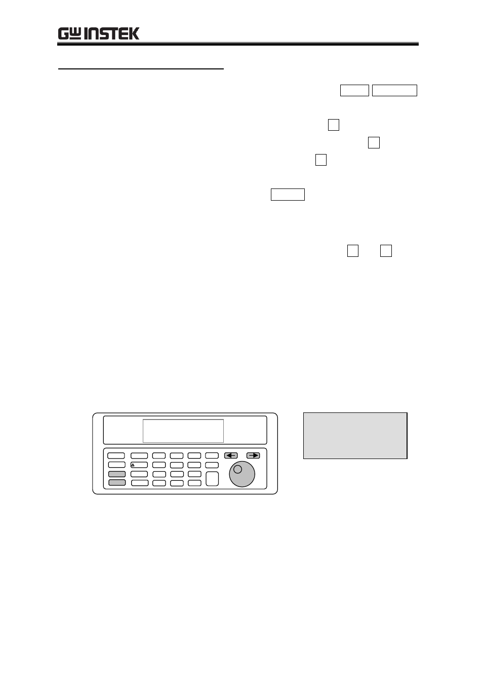
The optional tracking generator screen is accessed through the SHIFT TRK GEN
key. Upon entering the screen, 3 fields are displayed. The “TRK GEN” label
displays the status of the tracking generator. Pressing the
Í key will turn the
tracking generator on and off if the option is installed. Pressing the
Î key will
move the cursor to the NORMALIZE field. Pressing the
Î key once more will
activates the NORMALIZE function. Using the SPINNER allows the user to access
the second line. For convenience, pressing the ENTER key will move the cursor
through the different fields for easier operation.
The second line displays the tracking generator level and frequency offset (no label
for frequency offset). Both fields can be accessed by pressing the
Í and Î keys.
To change the fields, use the SPINNER. The numbers will scroll through the valid
range of values.
The normalize function allows the user to calibrate out the gains and losses in the
cables or other units under test. To use the normalize function, connect the
equipment to the tracking generator output port and the spectrum analyzer input
port. Following a normalize, the GSP-810 will factor out the measured variances.
When the Span or Center Frequency fields are changed, the normalize will be
reset and should be run again.
CENTER
SPAN
REF LVL
RBW
7
8
.
6
SHIFT
PK->MKR
MKR->CF
SETUP
TRACE
MKR
MKR
E
N
T
E
R
MHz
dBm
4
5
2
1
0
3
9
-
SPAN
CENTER
REF LVL
DEMOD
MEM
TRK GEN
RBW
PWR MTR
.
500.000MHz
20 dBm
100MHz/div
4 MHz
TRK GEN:◄OFF NORM►
LEVEL: 00dBm 00kHz
500.000MHz
20 dBm
100MHz/div
4 MHz
TRK GEN: ◄OFF NORM►
LEVEL: 00dBm 00kHz