0 setup and use – GW Instek GSP-810 User Manual User Manual
Page 13
GSP-810 User Manual
11
4.0 Setup and Use
4.1 General Description
The RF input is used to connect to the device under test, or to an external circuit or
antenna. The characteristic frequency and level of the signals received are
detected displayed on the CRT.
4.2 Use
The settings and control for the GSP-810 are easily accessed from the keypad.
The left column of keys are the field selections for Center Frequency (CENTER),
Span (SPAN) and Reference Level (REF LVL). Pressing one of these keys selects
the corresponding setting and screen edit field. The BLUE alternate function key is
used to access the functions identified by the blue text above the respective key.
For instance, pressing BLUE followed by MEMORY selects the TRACE functions.
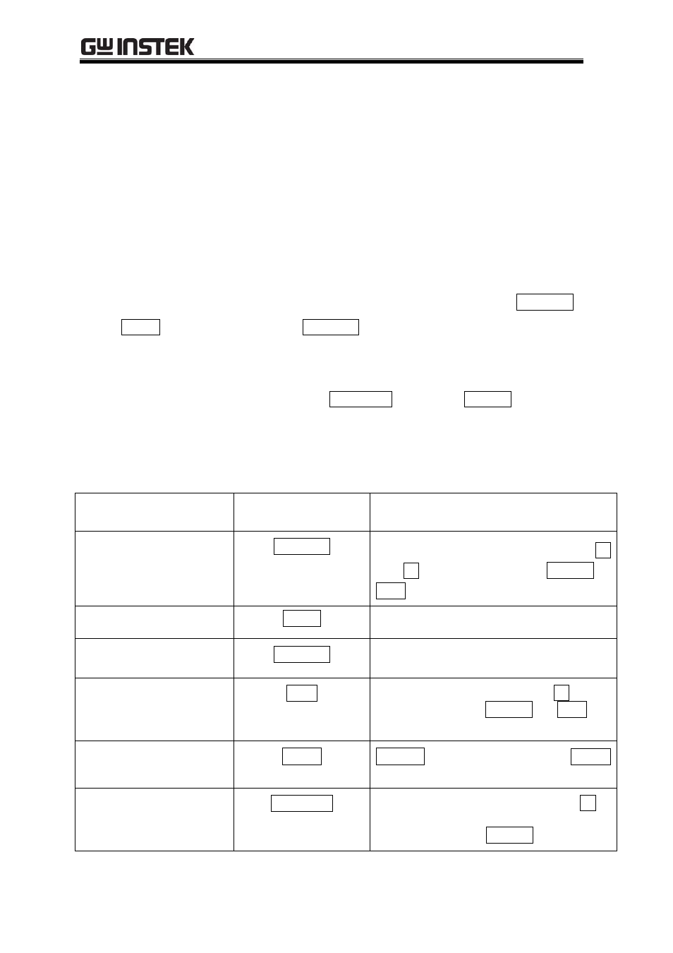
The following table contains a list of the various data fields that may be controlled
within the GSP-810, the selection for the field and the means to change or enter
data into the field.
Field
Selection Key
Data Entry
Center Frequency
CENTER
0-9, "." to directly enter a value;
Í
and
Î SPINNER to scroll ENTER or
MHz to complete
Frequency Span
SPAN
SPINNER to scroll
Reference Level
REF LVL
SPINNER to scroll
Markers
MKR
SPINNER to select #1 or #2;
Î to edit
selected marker; ENTER or MHz to
complete
Delta Marker
ΔMKR
ΔMARK to select Delta mode; MARK
to end Delta Mode
Memory Storage /
Recall
MEMORY
SPINNER select Recall or Save;
Î to
edit Recall / Save number; SPINNER
scrolls numbers; ENTER to complete