GW Instek GDS-122 User Manual User Manual
Page 9
Using
the
Oscilloscope
17
power cord if the level is < 25%.
>
75%
75%
50%
25%
< 25%
Switching the
operation mode
If the multimeter screen appears,
press the DMM/OSC key and change
the mode to oscilloscope.
DMM/OSC
Tilt standing the
GDS-122
Use the bar at the back to
tilt stand the GDS‐122 on a
horizontal plane.
Note
If pressing the power switch does not turn on the
GDS‐122, the battery may need recharging.
Connect the GDS‐122 to the AC adaptor and
recharge it for at least 15 minutes.
20B
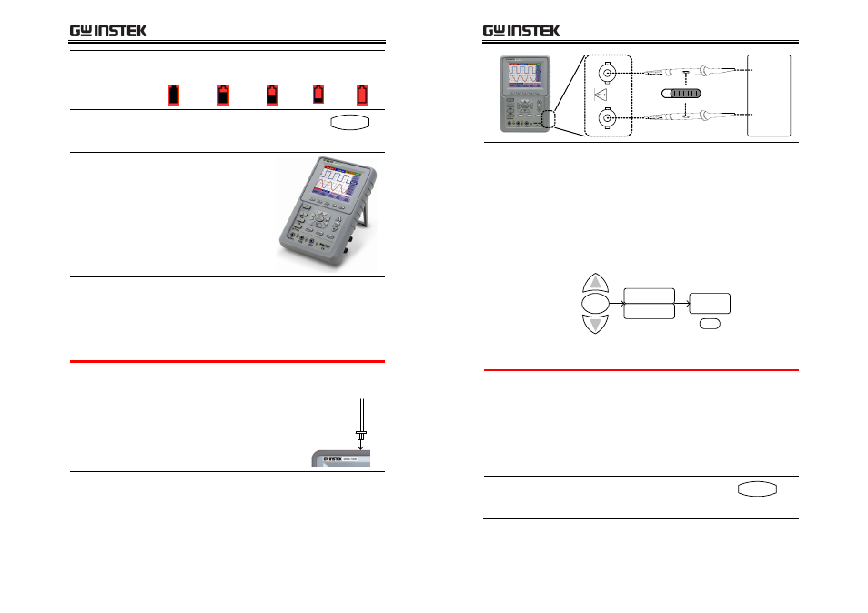
2. Connecting an input signal
1. Connecting
the probe
Connect the probe(s) between the DUT (Device
Under Test) and the CH1/2 inputs on the GDS‐122.
Alternately, you may use the
GDS‐122’s own 1kHz square
wave output signal. Insert the
signal cable (included in the
package) to the output terminal.
2. Setting the
probe
attenuation
To prevent excessive input voltage, we
recommend you to set the probe attenuation level
to the X 10 position to prevent excessive voltage.
GDS-122 User Manual
18
DUT or
1kHz square
wave
CA
T I
I
400
V
CH2
CH1
X10
X1
X10
X1
X1
X10
3. Setting the
display
magnification
1. After attenuating the probe level by x10, you
also need to magnify the display level by x10
to match the displayed amplitude with the real
amplitude. Open the CH1 or CH2 SETUP
menu by pressing the MENU key and using
the Up/Down keys.
2. Select the probe attenuation level (10X) by
pressing F3 (Probe) repeatedly. The CH1/CH2
vertical scale indicator at the bottom left corner
of the display changes accordingly.
10 X
Probe
CH2 SETUP
F3
MENU
CH1 SETUP
21B
3. Using the Autoset function
Overview
The Autoset function automatically configures the
following parameters according to the input
signal.
•
CH1/CH2 on/off
•
Vertical scale/level
•
Horizontal scale/level
•
Trigger level
Using the
Autoset function
Press the AUTOSET key. The input
signal appears in the best display
condition.
AUTOSET
(Continued on next page)