Configurations – GW Instek GDS-122 User Manual User Manual
Page 11
Using
the
Oscilloscope
21
24B
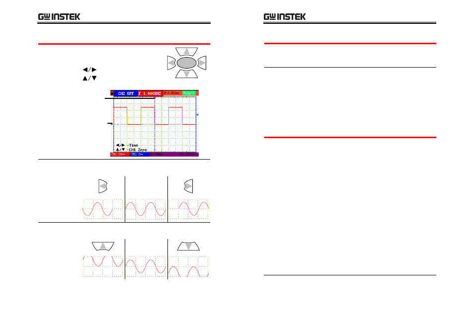
6. Adjusting waveform positions
Selecting the
menu
Press the OSC OPTION key
repeatedly until the following
menu appears on the display.
– Time
– CH1 (or CH2) Zero
OSC
OPTION
Vertical
center
position
Horizontal
center
position
Use the Left/Right key to change the horizontal
position.
Adjusting the
horizontal
position
Original
Use the Up/Down key to change the vertical
position.
Adjusting the
vertical position
Original
GDS-122 User Manual
22
5B
Configurations
Overview
The configuration chapter describes how to
change various GDS‐122 internal parameters for
allowing better measurement condition.
Configuration
items
•
Channel (vertical) settings
•
Horizontal settings
•
Trigger settings
•
Acquisition modes
•
Display settings
•
System status (only for viewing)
page
120H
22
page
121H
25
page
122H
25
page
123H
30
page
124H
36
page
125H
37
25B
Configuring channel (vertical) settings
Overview
The channel settings configure how the waveform
appears in terms of vertical or voltage scale.
Position
Sets the vertical position of the
waveform.
Scale
Sets the vertical scale (volts per
graticule). Range: 5mV/div to 5V/div
CH on/off Turns the channel on or off.
Coupling Selects AC or DC coupling. The DC
coupling shows all signal elements,
while the AC coupling filters out the
DC component from the waveform.
Inversion Flips the waveform upside down.
Magnifica
‐tion
Magnifies the displayed units (does not
magnify the real signal). The
magnification function is useful to
align the displayed with probe
attenuation (page
126H
17), especially X10.