133h, 134h – GW Instek GDS-122 User Manual User Manual
Page 15
Using
the
Oscilloscope
29
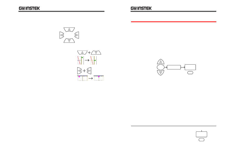
Use the arrow keys to change the triggering
position.
Move the trigger
point up
Move the trigger
point down
Move the
trigger point
right
Move the
trigger point
left
Pressing the Up and Down
key together resets the
vertical trigger level to zero.
Pressing the Left and Right
key together resets the
horizontal trigger level to
zero.
GDS-122 User Manual
30
28B
Configuring trigger settings: edge triggering
Overview
The edge trigger type triggers on the incoming
signal edge. Use the edge trigger for all signals
except for video related ones.
•
For general trigger settings, see page
133H
27.
•
For video triggering details, see page
134H
33.
To select edge triggering, follow these steps.
1. Press the MENU key and use the Up/Down
keys to select TRIG MODE menu.
2. Press F1 (Type) to select the Edge trigger type.
MENU
TRIG MODE
Edge
TYPE
F1
Slope
Selects the slope, rising or falling, on
which the GDS‐122 triggers the input
signals.
Source
Selects the signal source channel,
CH1 or CH2.
Mode
Selects the triggering mode, Auto
(acquires signal continuously),
Normal (acquires signal when trigger
conditions are met), and Single
(manually triggers the signal).
Coupling
Selects the DC or AC coupling and
rejection filters: high frequency or
low frequency.
Selecting the
trigger slope
Press F2 (Slope) repeatedly to
select the rising or falling slope.
Falling
Slope
Rising
F2
(Continues to the next page)