168h, 169h, 170h – GW Instek GDS-122 User Manual User Manual
Page 24: 171h, 172h, 173h
Using
the
Oscilloscope
47
38B
Viewing waveforms in X-Y format
Overview
The X‐Y format plots the CH1 input as X‐axis and
CH2 input as Y‐axis. This display mode is
convenient for viewing the phase relationship
between CH1 and CH2.
Panel operations
1. Make sure that both CH1 and CH2 waveforms
appear in the display.
2. Press the MENU key and
select the DISP SET menu
using the Up/Down keys.
MENU
DISP SET
3. Press F3 (Format) and select
XY. The display mode
switches into the X‐Y format.
XY
Format
F3
Changing the
scale and
position
Press the OSC OPTION key
repeatedly to access the menu listed
below. In the X‐Y mode, all scales and
positions are controlled by the
Up/Down keys.
OSC
OPTION
•
CH1 Zero: horizontal position
•
CH2 Zero: vertical position
•
CH1 Vol: horizontal scale
•
CH2 Vol: vertical scale
Functions not
applicable in the
X-Y format
The following functions do not work in the X‐Y
format.
•
Cursor measurement (page
168H
42, page
169H
43)
•
Automatic measurement (page
170H
41)
•
Window zoom (page
171H
45)
•
Trigger settings configuration (page
172H
25)
GDS-122 User Manual
48
39B
Viewing signal peaks
Overview
Using the peak detect acquisition mode, the
maximum and minimum data in the sampling
interval are displayed, capturing the rapid
changes and sudden peaks that might
spontaneously occur in a waveform.
Note
Since the peak detect mode picks up the most
extreme data, the waveform becomes noisier than
the normal acquisition mode (sampling mode).
Panel operations
1. Press the MENU key and use the Up/Down
keys to select ACQU MODE menu.
2. Press F2 (Peak Detect) to activate the peak
detect mode.
MENU
ACQU MODE
Peak
Detect
F2
For other acquisition settings details, see page
173H
30.
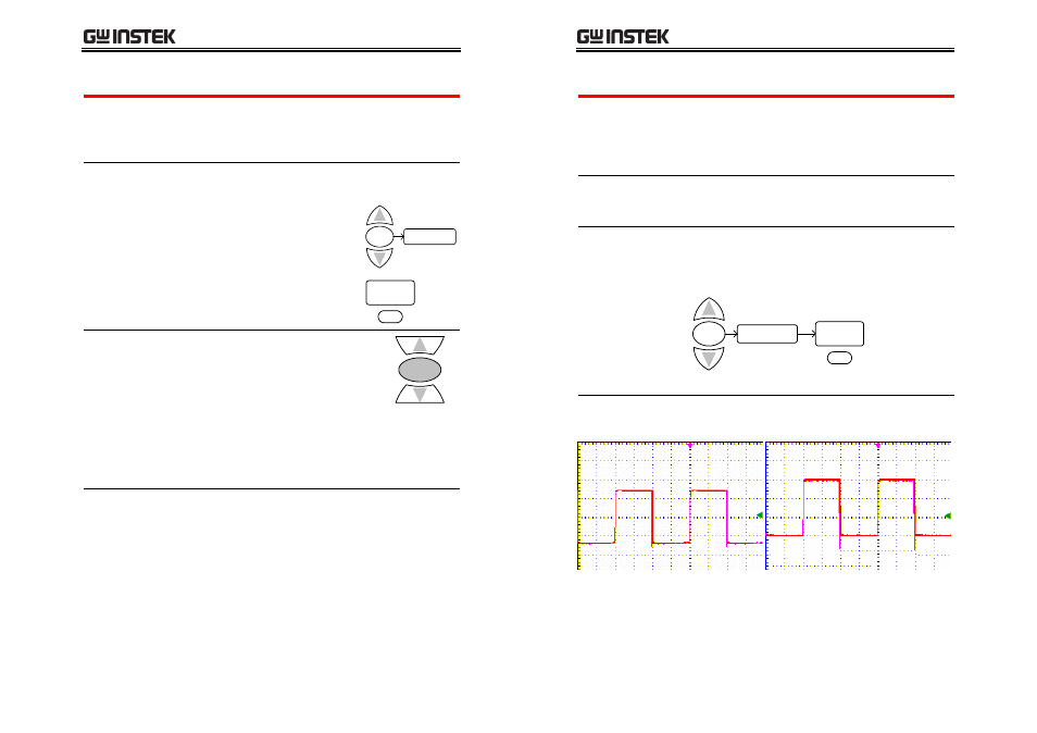
Example
Peak detect off
Peak detect on