135h – GW Instek GDS-122 User Manual User Manual
Page 16
Using
the
Oscilloscope
31
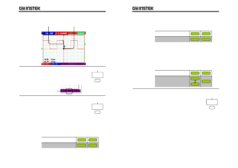
Example:
falling
edge
Triggering point
Falling edge
Selecting the
source channel
Press F3 (Channel) repeatedly to select
the trigger source channel, CH1 or
CH2. The trigger channel indicator at
the bottom right corner of the display
changes.
Trigger source
channel
CH1
Source
CH2
F3
Selecting the
trigger mode
Press F4 (Mode) repeatedly to select
the trigger mode. The trigger status
icon in the upper right corner of the
display changes accordingly. For the
overview of trigger status in general,
see page
135H
27.
Single
Mode
Auto
Normal
F4
Auto mode
In the auto mode, input signals are constantly
acquired and shown in the display regardless of
trigger condition.
100ms
5s
5ns
AUTO
Trig’d
Scan
Status icon when triggered
Status icon when not triggered
Scan
Horizontal scale (/div)
GDS-122 User Manual
32
Normal mode
In the normal mode, input signals are shown in
the display only if the trigger condition is met.
100ms
5s
5ns
Trig’d
Scan
Status icon when triggered
Status icon when not triggered
Scan
Horizontal scale (/div)
Ready
Single mode
In the single mode, you manually trigger the GDS‐
122 by pressing the RUN/STOP key each time you
need to observe the waveform. Once the waveform
is captured, the GDS‐122 stops triggering and
waits for the next trigger command.
STOP
100ms
5s
5ns
Status icon when triggered
Status icon when not triggered
Scan
Horizontal scale (/div)
STOP
AUTO
Ready
Selecting the
coupling mode
Press F5 (Coupling) repeatedly to select
the trigger coupling.
•
AC: triggers only on the AC portion
of the waveform.
•
DC: triggers on the whole waveform
(AC + DC).
•
LF Rjc: filters out the lower
frequency when triggering.
•
HF Rjc: filters out the higher
frequency when triggering.
DC
Coupling
AC
LF Rjc
HF Rjc
F5