136h, 137h – GW Instek GDS-122 User Manual User Manual
Page 17
Using
the
Oscilloscope
33
29B
Configuring trigger settings: video triggering
Overview
The video trigger type is designed to capture the
video signal format, NTSC, PAL, or SECAM. For
any other signal type, use the edge trigger.
•
For general trigger settings, see page
136H
27.
•
For edge triggering details, see page
137H
30.
To select edge triggering, follow these steps.
1. Press the MENU key and use the Up/Down
keys to select TRIG MODE menu.
2. Press F1 (Type) to select the video trigger type.
MENU
TRIG MODE
Video
TYPE
F1
Polarity
Selects the polarity of
synchronization signal. Normal
means the black level is low. Invert
means the black level is high.
Source
Selects the signal source channel,
CH1 or CH2.
Sync
Selects the part of the video signal
used for synchronization: line or
field.
Selecting the
trigger polarity
Press F2 (Polarity) repeatedly to select
the polarity of synchronization signal.
•
Normal: the black level is low.
•
Inverted: the black level is high.
Normal
Polarity
Inverted
F2
(Continues to the next page)
GDS-122 User Manual
34
Selecting the
source channel
Press F3 (Channel) repeatedly to select
the trigger source channel, CH1 or
CH2. The trigger channel indicator at
the bottom right corner of the display
changes.
Trigger source
channel
CH1
Source
CH2
F3
Selecting the
sync
Press F4 (Polarity) repeatedly to select
the synchronization point.
•
Line: the video line is used for
triggering.
•
Field: the video field is used for
triggering.
Line
Sync
Field
F4
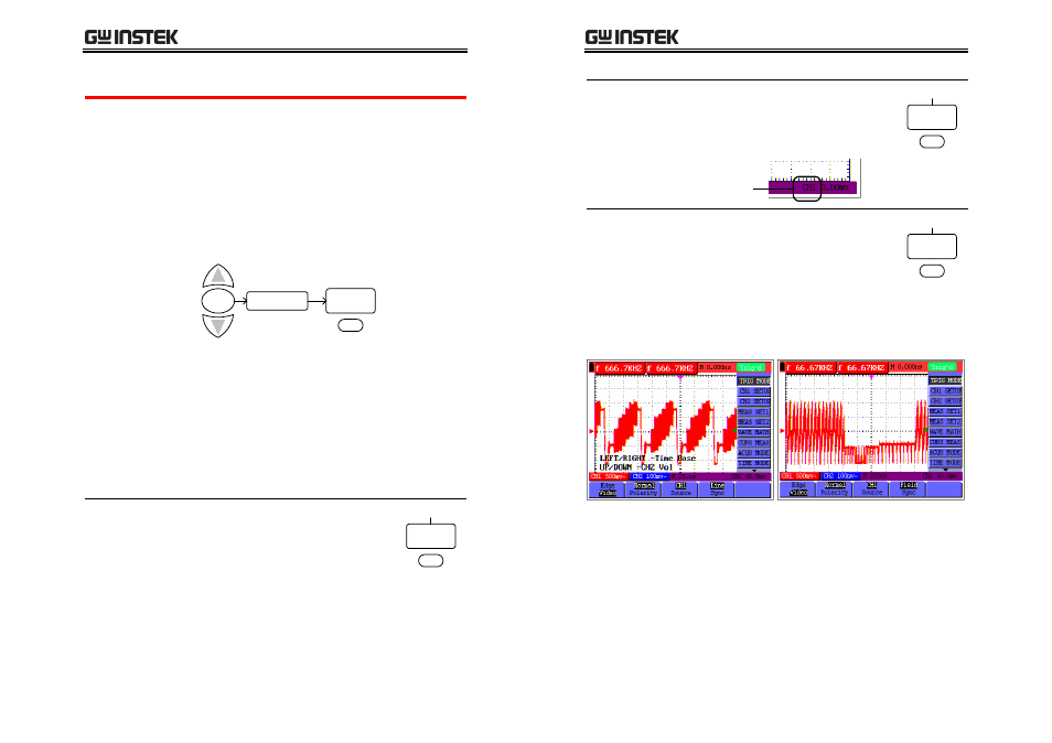
Example
Video line trigger
Video field trigger