Vertical controls – GW Instek GOS-630FC User Manual
Page 9
PANEL
OVERVIEW
17
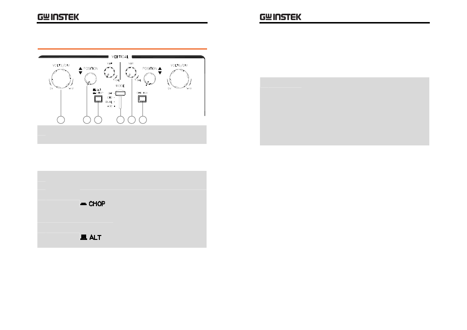
Vertical Controls
1
6
5
4
3
2
1 VOLTS/DIV
Knob
Controls the CH1/CH2 vertical scale from
1mV/DIV to 5V/DIV in 12 steps.
2 Vertical
POSITION
Knob
Controls the vertical position of traces and light
spots for CH1/CH2.
3 ALT/CHOP
Switch
Selects how the CH1 and CH2 signals appear in the
display, in the DUAL trace mode.
CHOP
The two signals are chopped and
displayed simultaneously (generally
used in slow sweep, 1ms/DIV or
slower).
ALT
The two signals are displayed
alternatively (generally used in fast
sweep, 0.5ms/DIV or faster).
4 Vertical
MODE
Switch
Selects CH1 and CH2 display modes.
CH1/CH2 The CH1 or CH2 signal is displayed
independently.
GOS-630FC
User
Manual
18
DUAL
The CH1 and CH2 signals are displayed
simultaneously.
ADD
The CH1 and CH2 signals are added or
subtracted, and then the result is
displayed. For CH1/CH2
addition/subtraction details, see page31.
5 VAR Knob Adjusts the vertical scale.
At the minimum position, the vertical scale
becomes 2.5 times wider than the original value
selected by the VOLTS/DIV knob. For example, if
the original scale is 1mV/DIV, the adjusted scale
becomes 2.5mV/DIV.
At the maximum (CAL) position, there is no
change in the vertical scale.
6 CH2 INV
Switch
Inverts the CH2 input signal vertically. When the
vertical mode switch is in the ADD position, CH2 is
subtracted from CH1 instead of being added to
CH1. For CH1/CH2 addition/subtraction details,
see page31.