Waveform addition/subtraction, Frequency measurement, X-y mode – GW Instek GOS-630FC User Manual
Page 16
MEASUREMENT
31
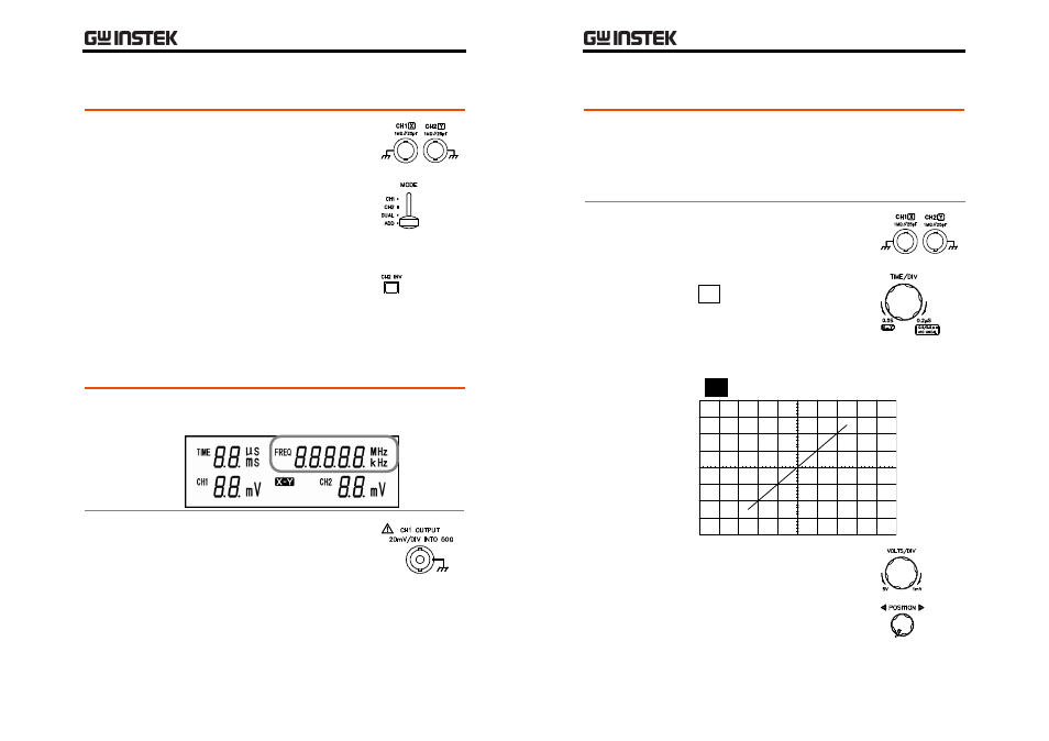
Waveform Addition/Subtraction
Steps
1. Make sure both CH1 and CH2
waveforms appear on the
display. For details, see page29.
2. Set the vertical MODE switch to
the ADD position. The two
waveforms are added and
appear on the display as a
single waveform.
3. To subtract the CH2 signal from
the CH1 signal, invert the CH2
signal by pressing the CH2 INV
switch.
Frequency Measurement
Frequency
shown on the
LCD
The frequency of the input signal appears on the
LCD display and is constantly updated.
Frequency
measurement
using the CH1
output
The CH1 signal frequency can be
measured using an external device
such as frequency counter, via the
rear panel terminal.
GOS-630FC
User
Manual
32
X-Y Mode
Background
The X‐Y mode compares the amplitude of two
signals (CH1 and CH2), one as X‐axis (CH1) and
the other as Y‐axis (CH2). The X‐Y mode is useful
for measuring the phase difference of two signals,
video color patterns, and frequency response.
Steps
1. Make sure both CH1 and CH2
waveforms appear on the
display. For details, see page29.
2. Move the TIME/DIV knob to the
X‐Y position.
3. The CH1 and CH2 signals appear in the X‐Y
mode and the X‐Y indicator in the LCD display
(
X‐Y
) turns on.
4. To adjust the X‐axis position and
deflection, use the horizontal
POSITION knob (position) and
CH1 VOLTS/DIV knob
(deflection).