Anel overview, Front panel overview, Display controls – GW Instek GOS-630FC User Manual
Page 7
PANEL
OVERVIEW
13
P
ANEL OVERVIEW
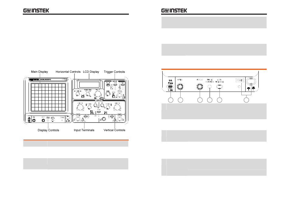
Front Panel Overview
Detailed descriptions of each block start from the next page.
Main Display Shows the waveforms of input signals.
Display
Controls
Controls power on/off, display configuration, and
the probe compensation output.
LCD Display Shows the vertical scale, horizontal scale, X‐Y
display mode, and waveform frequencies.
Horizontal
Controls
Controls the horizontal scale, horizontal position,
sweep length, and x10 magnification.
GOS-630FC
User
Manual
14
Vertical
Controls
Controls the vertical scale, vertical position, display
mode, CH2 inversion, and alternate display mode.
Trigger
Controls
Controls the trigger mode, trigger level, trigger
coupling source, trigger slope, and alternate
triggering mode. Accepts the external trigger input.
Input
Terminals
Accepts the CH1 and CH2 input signals and ground
wire. Controls the input signal coupling mode.
Display Controls
6
5
4
3
2
1
1 CAL Output Generates the probe compensation signal; 2Vp‐p,
1kHz, positive square wave. For probe
compensation details, see page26.
2 INTEN Knob Controls the brightness of a light spot or trace in
the display.
3 FOCUS
Knob
Controls the focus (sharpness) of the waveforms in
the display.
4 TRACE
ROTATION
Point
Controls the alignment of the horizontal trace in
parallel with graticule lines.
5 AUTO
TIMEBASE
Key
Automatically adjusts the horizontal scale to an
appropriate range according to the input signal.
6 POWER
Switch
Turns on or off the oscilloscope’s main power.
When the power is on, the LED lights.