Trigger controls – GW Instek GOS-630FC User Manual
Page 10
PANEL
OVERVIEW
19
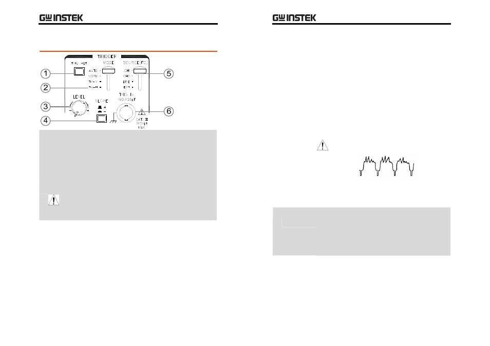
Trigger Controls
1 Trigger ALT
Switch
When pressed, the TRIG ALT switch constantly
toggles the trigger source between CH1 and CH2
signal, so that both signals can be clearly viewed.
The TRIG ALT switch works when the vertical
mode is in the DUAL position and also the trigger
source is in the CH1 or CH2 position.
Note
•
The TRIG ALT switch does not work when the
ALT/CHOP switch is in the CHOP position.
•
The frequency counter in the LCD display does
not work when the TRIG ALT switch is pressed.
2 Trigger
MODE
Switch
The TRIGGER MODE switch selects when the
oscilloscope responds to the trigger conditions.
AUTO
The oscilloscope sweeps regardless of
the existence of trigger conditions.
NORM
The oscilloscope sweeps only when a
trigger condition occurs.
GOS-630FC
User
Manual
20
TV-V
The oscilloscope triggers when a
vertical video synchronization signal
appears. For triggering on the field,
select 2ms/DIV as the horizontal scale;
for triggering on the frame (two
interlaced fields), 5ms/DIV.
TV-H
The oscilloscope triggers when a
horizontal video synchronization
signal appears. For triggering on the
line, select 10us/DIV as the horizontal
scale. Use the SWP VAR knob to
control the number of waveforms.
Note
•
For TV‐V and TV‐H trigger, the
oscilloscope responds only to
negative polarity signals.
•
The oscilloscope cannot trigger
input signals when their
frequencies are less than 25Hz.
3 Trigger
LEVEL Knob
Changes the trigger level vertically.
The trigger level moves up when the trigger LEVEL
knob is turned clockwise.
The trigger level moves down when the trigger
LEVEL knob is turned counterclockwise.