Dual channel measurement – GW Instek GOS-630FC User Manual
Page 15
MEASUREMENT
29
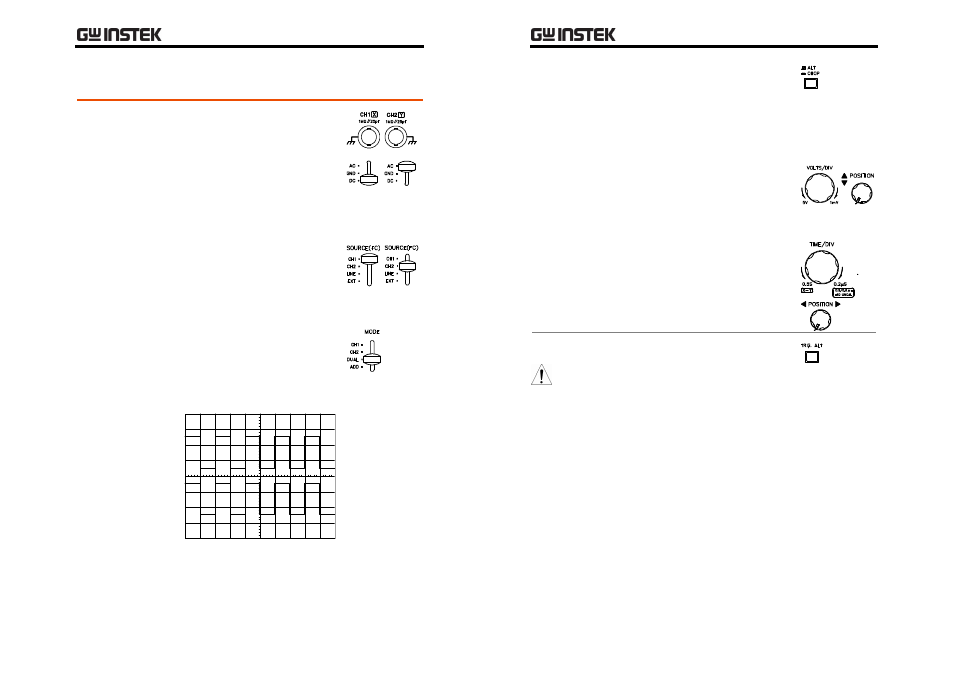
Dual Channel Measurement
Steps
1. Connect both CH1 and CH2
signals to the input terminals.
2. Select the vertical coupling
between AC (DC components
are blocked) or DC (all signal
components appear) for both
channels.
3. Configure the trigger settings.
For details, see page19.
Make sure the trigger SOURCE
switch is in either the CH1 or
CH2 position.
4. Set the vertical MODE switch to
the DUAL position.
5. Both the CH1 and CH2 signals appear on the
display.
GOS-630FC
User
Manual
30
6. Use the vertical ALT/CHOP
switch to select how the two
waveform appear on the
display: alternately (ALT mode)
or simultanouesly (CHOP
mode). See page17 for details.
7. If necessary, use the
VOLTS/DIV knob and vertical
POSITION knob to adjust the
vertical scale and position of
the waveform.
8. If necessary, use the TIME/DIV
knob and horizontal POSITION
knob to adjust the horizontal
scale and position of the
waveform.
Note
The trigger ALT switch does not
work when the ALT/CHOP switch
is in the CHOP position.
- GDB-03 (99 pages)
- GLA-1000 Series User Manual (111 pages)
- GLA-1000 Series Quick start guide (20 pages)
- GOS-635G (36 pages)
- GOS-6000 Series (27 pages)
- GOS-6103C (30 pages)
- GOS-6100 Series (30 pages)
- GRS-6000A Series (51 pages)
- GDS-122 Installation Guide (4 pages)
- GDS-122 User Manual (52 pages)
- GDS-2000A series CAN/LIN bus User Manual (18 pages)
- GDS-2000A series Quick start guide for DS2-FGN (6 pages)
- GDS-2000A series Freewave User Manual (26 pages)
- GDS-2000A series Quick start guide for Logic analyzer option (18 pages)
- GDS-2000A series Quick start quide for DS2-LAN (2 pages)
- GDS-2000A series Option User Manual (80 pages)
- GDS-2000A series User Manual (261 pages)
- GDS-2000A series Programming Manual (272 pages)
- GDS-2000A series Single sheet for LA Quick start guide (2 pages)
- GBS-1000 Series Programming Manual (88 pages)
- GBS-1000 Series User Manual (187 pages)
- GDS-1000-U Series firmware upgrade (1 page)
- GDS-1000-U Series Programming Manual (70 pages)
- GDS-1000-U Series Quick start guide (2 pages)
- GDS-1000-U Series User Manual (133 pages)
- GDS-1000A-U Series Programming Manual (88 pages)
- GDS-1000A-U Series Quick start guide (2 pages)
- GDS-1000A-U Series User Manual (148 pages)
- GDS-3000 Series GCP-530/1030 current probe User Manual (40 pages)
- GDS-3000 Series GDP-025/050/100 differential probe User Manual (21 pages)
- GDS-3000 Series DS3-PWR Power analysis manual (37 pages)
- GDS-3000 Series User Manual (209 pages)
- GDS-3000 Series Programming Manual (103 pages)
- GDS-3000 Series DS3-SBD Serial Bus decode (29 pages)
- GDS-3000 Series GKT-100 deskew fixture User Manual (1 page)
- GDS-3000 Series GUG-001, GPIB to USB adapter User Manual (15 pages)
- GDS-300 Series User Manual (188 pages)
- GDS-300 Series Programming Manual (139 pages)
- GDS-300 Series Quick start guide (21 pages)
- GRF-3300 Series Student Manual (26 pages)
- GRF-3300 Series Teacher Manual (26 pages)
- GRF-1300A (124 pages)
- GSP-810 User Manual (40 pages)
- GSP-810 Software Manual (3 pages)