Easurement, Single channel (basic) measurement – GW Instek GOS-630FC User Manual
Page 14
SETUP
27
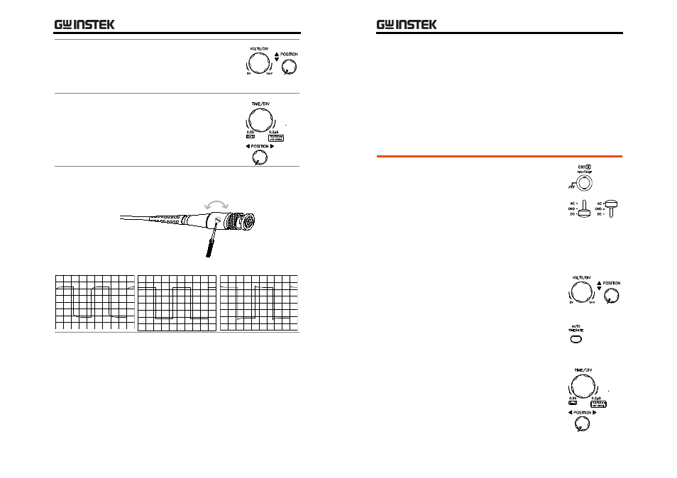
6 Vertical
adjustment
Use the CH1 VOLTS/DIV knob
and CH1 vertical POSITION knob
to adjust the vertical scale and
position of the waveform.
7 Horizontal
adjustment
Use the CH1 TIME/DIV knob and
CH1 horizontal POSITION knob to
adjust the horizontal scale and
position of the waveform.
Adjust the compensation point on the probe so
that the waveform becomes square.
8 Probe
compensa-
tion
Under compensation
Right amount
Over compensation
9 Completion Now setting up the oscilloscope is completed. For
more advanced measurements, see page28.
GOS-630FC
User
Manual
28
M
EASUREMENT
Single Channel (Basic) Measurement
Steps
1. Connect the input signal to the
CH1 or CH2 terminal.
2. Select the vertical coupling
between AC (DC components
are blocked) or DC (all signal
components appear).
3. Configure the trigger settings.
For details, see page19.
4. Use the VOLTS/DIV knob and
vertical POSITION knob to
adjust the vertical scale and
position of the waveform.
5. Press the AUTO TIMEBASE
key to automatically adjust the
horizontal scale according to
the input signal.
6. If necessary, use the TIME/DIV
knob to adjust the horizontal
scale manually. Use the
horizontal POSITION knob to
adjust the position of the
waveform.