Input terminals – GW Instek GOS-630FC User Manual
Page 11
PANEL
OVERVIEW
21
4 Trigger
SLOPE
Switch
Selects the triggering slope.
When in the “+” position (
), the oscilloscope
triggers when the positive slope of the trigger
source signal crosses the trigger level.
When in the “–” position (
), the oscilloscope
triggers when the negative slope of the trigger
source signal crosses the trigger level.
5 Trigger
SOURCE
Switch
Selects the signal on which the oscilloscope sweeps.
CH1
CH1 signal becomes the trigger
source.
CH2
CH2 signal becomes the trigger
source.
LINE
AC power line signal becomes the
trigger source. Useful when the input
signal synchronizes with the power
line frequency.
EXT
The external trigger input (TRIG IN
terminal) signal becomes the trigger
source.
6 TRIG IN
Terminal
Accepts an external trigger source signal. The
signal becomes active when the trigger SOURCE
switch is in the EXT position.
Input impedance: 1MΩ // 25pF
GOS-630FC
User
Manual
22
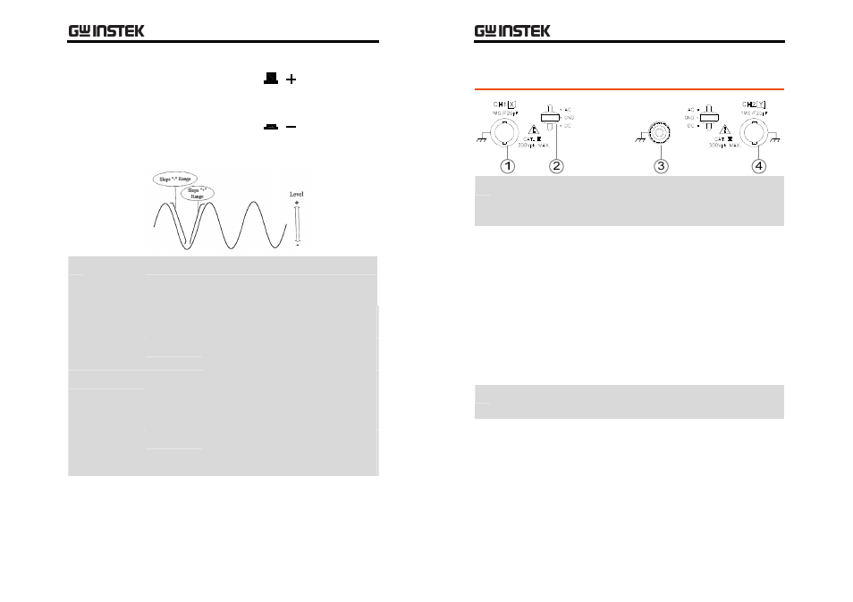
Input Terminals
1 CH 1 (X)
Input
Terminal
Accepts the CH1 input signal. In X‐Y mode, the
CH1 input signal becomes the X‐axis.
2 AC/GND/
DC Switch
Selects the coupling mode for the input signal.
AC
The oscilloscope block DC components
included in the input signal.
GND
Shows the ground (zero volt) level on
the display. This mode is only for
checking the reference level; input
signal does not appear on the display.
DC
The oscilloscope displays all of the
input signal.
3 GND
Terminal
Accepts a ground wire. The GND terminal is
connected to the oscilloscope mainframe.
4 CH 2 (Y)
Input
Terminal
Accepts the CH2 input signal. In X‐Y mode, the
CH2 input signal becomes the Y‐axis.
•
For X‐Y mode details, see page32.