Etup, Rear panel overview, Default settings – GW Instek GOS-630FC User Manual
Page 12
PANEL
OVERVIEW
23
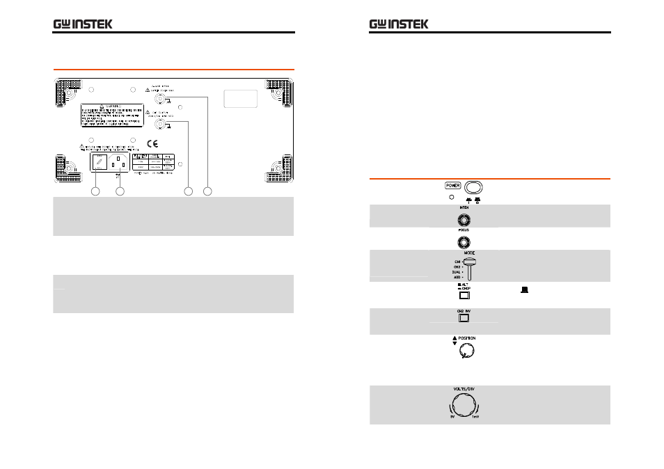
Rear Panel Overview
2
1
3
4
1 FUSE & Line
Voltage
Selector
Holds the AC mains fuse and selects the AC line
voltage, 115V or 230V.
2 AC Power
Input
Connector
Accepts the AC power cord.
3 CH1
OUTPUT
Terminal
Outputs the CH1 signal; approximately 20mV/DIV
when terminated with 50Ω.
4 Z AXIS
INPUT
Terminal
Accepts an external intensity modulation (Z‐axis)
signal; 1kHz square wave, DC – 2MHz. Positive
going reduces intensity. For detailed specifications,
see page38.
•
For AC line voltage selection and fuse replacement, see page36.
GOS-630FC
User
Manual
24
S
ETUP
Default Settings
Before powering up the oscilloscope, set up the front panel as
follows.
POWER Switch
Off
INTEN Knob
Center
FOCUS Knob
Center
Vertical MODE
Switch
CH1
ALT/CHOP
Switch
ALT (
)
CH 2 INV
Switch
Released (Inversion disabled)
CH1/CH2
Vertical
POSITION
Knob
Center of the display
CH1/CH2
VOLTS/DIV
Knob
50mV/DIV
- GDB-03 (99 pages)
- GLA-1000 Series User Manual (111 pages)
- GLA-1000 Series Quick start guide (20 pages)
- GOS-635G (36 pages)
- GOS-6000 Series (27 pages)
- GOS-6103C (30 pages)
- GOS-6100 Series (30 pages)
- GRS-6000A Series (51 pages)
- GDS-122 Installation Guide (4 pages)
- GDS-122 User Manual (52 pages)
- GDS-2000A series CAN/LIN bus User Manual (18 pages)
- GDS-2000A series Quick start guide for DS2-FGN (6 pages)
- GDS-2000A series Freewave User Manual (26 pages)
- GDS-2000A series Quick start guide for Logic analyzer option (18 pages)
- GDS-2000A series Quick start quide for DS2-LAN (2 pages)
- GDS-2000A series Option User Manual (80 pages)
- GDS-2000A series User Manual (261 pages)
- GDS-2000A series Programming Manual (272 pages)
- GDS-2000A series Single sheet for LA Quick start guide (2 pages)
- GBS-1000 Series Programming Manual (88 pages)
- GBS-1000 Series User Manual (187 pages)
- GDS-1000-U Series firmware upgrade (1 page)
- GDS-1000-U Series Programming Manual (70 pages)
- GDS-1000-U Series Quick start guide (2 pages)
- GDS-1000-U Series User Manual (133 pages)
- GDS-1000A-U Series Programming Manual (88 pages)
- GDS-1000A-U Series Quick start guide (2 pages)
- GDS-1000A-U Series User Manual (148 pages)
- GDS-3000 Series GCP-530/1030 current probe User Manual (40 pages)
- GDS-3000 Series GDP-025/050/100 differential probe User Manual (21 pages)
- GDS-3000 Series DS3-PWR Power analysis manual (37 pages)
- GDS-3000 Series User Manual (209 pages)
- GDS-3000 Series Programming Manual (103 pages)
- GDS-3000 Series DS3-SBD Serial Bus decode (29 pages)
- GDS-3000 Series GKT-100 deskew fixture User Manual (1 page)
- GDS-3000 Series GUG-001, GPIB to USB adapter User Manual (15 pages)
- GDS-300 Series User Manual (188 pages)
- GDS-300 Series Programming Manual (139 pages)
- GDS-300 Series Quick start guide (21 pages)
- GRF-3300 Series Student Manual (26 pages)
- GRF-3300 Series Teacher Manual (26 pages)
- GRF-1300A (124 pages)
- GSP-810 User Manual (40 pages)
- GSP-810 Software Manual (3 pages)