Detcon X40-32-N7 User Manual
Page 32
Model X40
Model X40 Instruction Manual
Rev. 3.3
Page 26 of 64
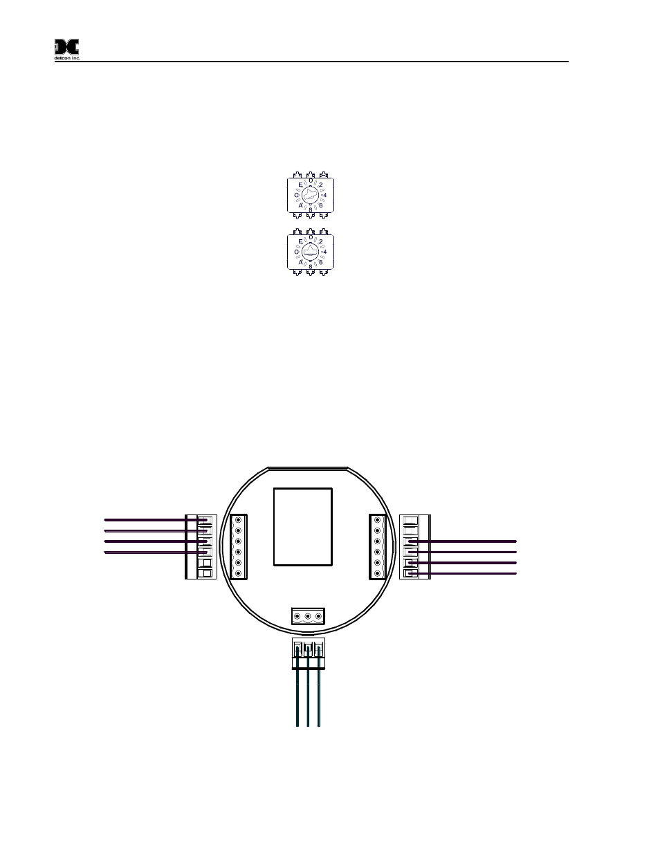
3. Ensure that the two rotary switches on the Model 100 Terminal Board are set to the Modbus™
address (F0h) for the wireless radio module of the X40 controller. The Model 100 Terminal Board
should come set from the Detcon factory and should be set to the address to F0h. Access the
terminal board and locate the switches shown in Figure 25. The MSD (most significant digit) "F" is
represented by the top rotary switch (closest to the J1 connector) and the LSD (least significant
digit) "0" is represented by the bottom rotary switch (closest to the J2 connector).
Figure 25 Model 100 Terminal Board Rotary Switches
4. Install the battery in the condulet and observe that the controller display starts and the unit will go
through the boot-up sequence (Section 3.12).
AC Operated Units
Units that have a Transceiver, and come supplied with the AC/DC Converter need only have AC voltage
applied to operate properly
1. Attach the mounting plate assembly to a pole with two U-Bolts secured through the 7/16" rectangle
holes of the mounting plate base (Figure 23).
V
A
C
(N
)
V
A
C
(L
)
G
N
D
AC Power from
External Voltage Source
Customer Supplied Wiring
(In)
G
rn
W
h
t
B
lk
B1(-)
A1(+)
PWR(+)
GND(-)
Wiring to X40 Controller
Wiring to Transceiver
A1(+)
B1(-)
GND
24VDC
Not Used
Not Used
+24V
GND
A
C
D
B
D
C
B
GND
+24V
A
J1
J2
J3
U1
N
L
E
AC IN
Figure 26 N7 AC/DC Converter Board Wiring with Transceiver