Detcon X40-32-N7 User Manual
Page 20
Model X40
Model X40 Instruction Manual
Rev. 3.3
Page 14 of 64
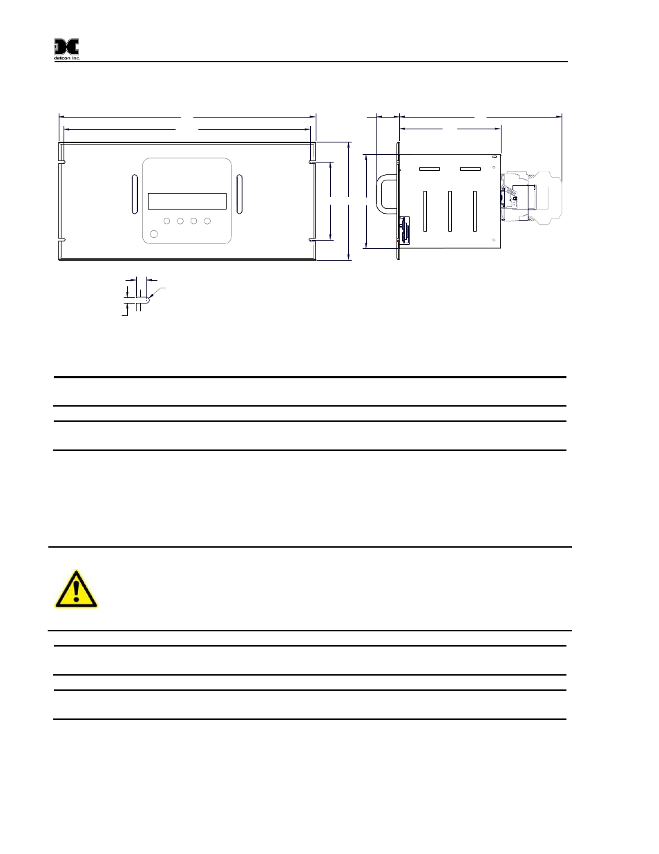
Figure 6 N1P Controller Mounting and Dimensional View
5.75" 8.7"
7.5"
1.7"
12"
0.218"
0.375"
R0.109"
Slot Detail
18.25"
19"
6.94"
Figure 7 N1R Controller Mounting and Dimensional View
NOTE
If the AC and DC wiring are run in conduit, ensure that the AC wiring is not housed in the
same conduit as the DC signal/wiring
NOTE
The power supply for the X40-32-N1P and X40-32-N1R is capable of handling AC inputs
between 100-120/220-240VAC, 50-60Hz without degradation.
3. Install AC or DC power as follows: (Refer to Figure 8.)
a.
Install AC power by connecting the 100-120/220-240VAC input wiring to the terminals
labeled VAC (L1), NEU (L2), and GROUND.
b. Install DC power by connecting the 11.5-30VDC to the terminals of the DIN rail mounted
terminal block labeled 24VDC and DC Comm.
CAUTION
Equipment and equipment to be electrically connected shall use safety approved
wire/cable in conjunction with appropriate and compatible protective cable gland,
all of which meet the requirements of the max equipment rating (250VAC, 5A)
and any local electrical codes, regulations and standards. The cable used to
connect to the terminals of the X40-32-N1P and X40-32-N1R must be rated for a
minimum of 105ºC.
NOTE
The DC input voltage should be capable of delivering at least 4.2 Amps of current to the
load (100 Watts @ 24VDC).
NOTE
The supply of power should be from an isolated source with over-current protection and an
input voltage range between 11.5-30VDC.
4. Connect the external Modbus™ sensors at the RS-485 connections labeled RS-485 Master: ‘A’,
‘B’, and ‘Shld’ (Figure 8).