Nema7 units with rxt-320 transceiver, Figure 21 n7 dc power wiring – Detcon X40-32-N7 User Manual
Page 30
Model X40
Model X40 Instruction Manual
Rev. 3.3
Page 24 of 64
b. J1 should come wired and connected to the controller from the factory. Ensure that J1 is
properly connected to the AC/DC Converter.
c.
Interface the I/O modules and sensors to the X40 controller through the J2 connector of the
AC/DC converter board (Figure 21).
NOTE
The terminals on the J3 connector are labeled N (neutral), L (line power) and E (earth
ground).
NOTE
An optional Transient Protection board is available from Detcon for use with external DC
Supply. When using external DC power to power the controller the input power must be
11.5-30VDC.
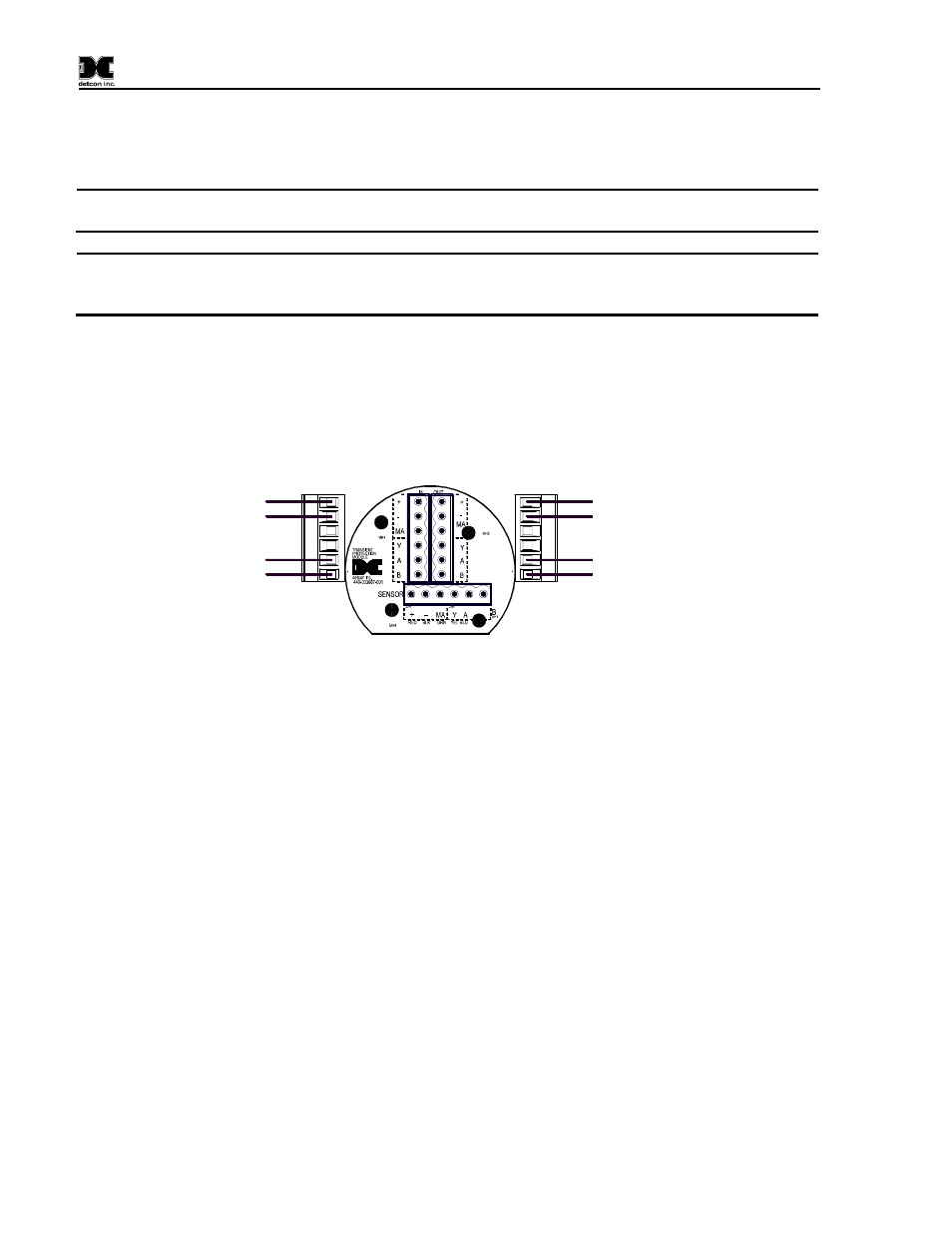
7. For units that will be wired to an external power source connect the external power and Modbus™
as follows:
a.
Connect the 11.5-30VDC to the terminals Labeled “+” and “-“ on the transient Protection
PCA.
b. Connect the RS-485 Master Port to the terminals labeled “A” and “B” on the Transient
Protection PCA.
Wiring to
X40-32-N7 Controller
J7 Connector
Customer Supplied Wiring
VDC(+)
VDC(-)
A
B
VDC(+)
VDC(-)
A
B
11.5~30VDC
RS-485 Master Port
Figure 22 N7 DC Power Wiring
8. After applying power to the unit observe that the controller display starts and the unit will go
through the boot-up sequence (Section 3.12).
2.4.1
NEMA7 units with RXT-320 Transceiver
NEMA 7 units can come pre-configured with a RTX-320 Transceiver.
These units will come pre-
assembled on a mounting plate that can be mounted on a 2~3” pole.
Battery Operated Units
Battery operated units come prewired and set up for installation:
1. Attach the mounting plate assembly to a pole with two U-Bolts secured through the 7/16" rectangle
holes of the mounting plate base (Figure 23).
2. The wireless radio module connected to the Modbus™ master port is to be used with a Detcon
Smart Wireless battery pack.
These units come with the Model 100 Terminal Board will be
mounted in the condulet/J-Box (Figure 24). Refer to Table 1 for descriptions of the connector
plugs.
come as battery operated, DC or AC operated.