High-density cabling, Installing icl cables, High-density cabling installing icl cables – Brocade DCX 8510-4 Backbone Hardware Reference Manual User Manual
Page 30
NOTE
Do not route the cables in front of the air exhaust vent, which is located at the top of the port side of
the chassis. If you are using the Port Side Exhaust Kit with your Brocade DCX 8510-4, there is also an
exhaust vent at the bottom of the port side of the chassis. Use the cable management finger
assemblies to keep the cables away from this exhaust vent as well.
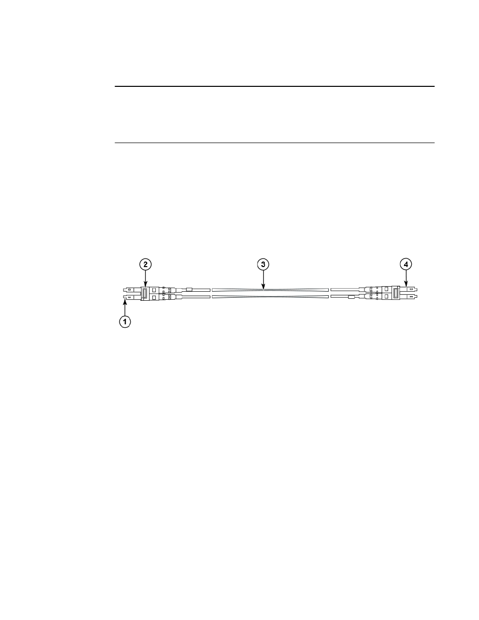
High-density cabling
The FC8-64 high density port blade cannot use the standard LC cables because the pitch between
optics in the new mini-SFP (mSFP) transceiver is smaller than in standard SFPs. Patch cables and
panels can be used to attach standard size cabling to the blade if necessary. The following figure
illustrates the mSFP to SFP patch cable. Refer to "Best Practices Guide: High Density Cable
Management Solutions" (available at
) for cable management guidelines for
high-density port solutions, and cable and patch panel part numbers.
FIGURE 4 Cable design for the mSFP patch cables for the FC8-64 high density port blade
1. mSFP connector
2. Duplex clip (black)
3. 6 mm cable
4. SFP connector
Note that the duplex clip on the mSFP end of the cable is black for easier recognition. For a listing of
the qualified mSFP optical cables for the FC8-64 port blade, refer to
Qualified cables for the FC8-64
on page 124.
If ISL Trunking is in use, group the cables by trunking group. The ports are color-coded to indicate
which ports can be used in the same ISL Trunking group: eight ports marked with solid black ovals
alternate with eight ports marked with oval outlines.
Installing ICL cables
Inter-chassis link (ICL) cable removal and replacement
on page 92 for the procedure to
install the ICL QSFP cables
High-density cabling
30
Brocade DCX 8510-4 Backbone Hardware Reference Manual
53-1002177-07