Yokogawa YVP20S User Manual
Page 63
7-2
<7. INTEGRATED VALVE INTERFACE (IVI)>
IM 21B04C50-01E
Menu items
Menu bar contains File, Setup, View, Tools, and Help menus.
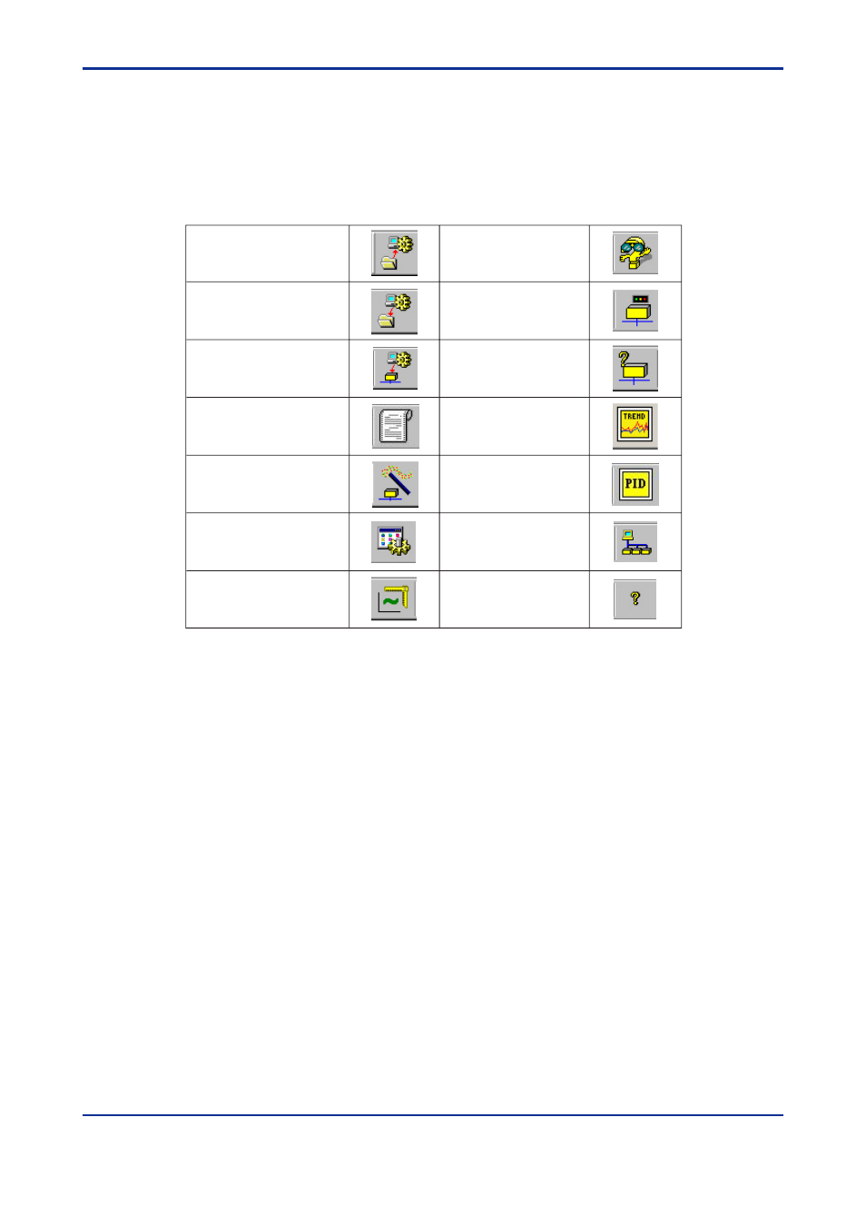
Toolbar icons
Toolbar services are listed below, in the order of the icons shown on the Toolbar. While a
function is disabled its icon is “grayed out.”
Table 7.1 Toolbar Icons
Diagnostics
Change device operation
state
Query device
View Trend
PID Process controller
Rescan the field bus
segment
About ValveNavi version
Open configuration file
Save Configuration file
Download configuration
Generate a report file
Setup Wizard
Configuration management
Calibration management
T0701.EPS
The positioner’s tag is shown in the PD Tag field. The current operating state of the
positioner is shown the text box. Individual block modes are displaye for each of the
positioners internal function blocks. The valve position Set Point is displayed by the graphi-
cal position of a slider and numerically to two decimal places. Below the setpoint display,
the target position and actual position are shown as a slider and bar respectively, with
values shown to two decimal places.
The Target Position is derived from the Set Point signal based on the parameters defined in
Configuration Services, as well as the characterization and the configuration of air-to-open
or air-to-close. If linear characteristics and air-to-open are configured, without limits, the
position setpoint is equal to input signal expressed in percentage. When the configuration
is nonlinear with limits, the incoming setpoint and the target position differ because the
Analog Output (AO) Block and Transducer (TB) Block re-compute the target to conform.