5 positioner signature, Positioner signature -20 – Yokogawa YVP20S User Manual
Page 146
14-20
<14. DIAGNOSTIC SERVICES>
IM 21B04C50-01E
14.3.5 Positioner Signature
This signature function measures the static characteristics of the control valve system.
eter
Input signal of the control valve system: Input signal of YVP110 (Equal to AO Block
OUT.Value)
Output signal of control valve system: Feedback signal of YVP110 (Equal to
FINAL_POSITION_VALUE.Value)
The Low Cut, High Cut, Position Characterization and other functions related to Positioning
in Transducer block are reflected in measuring Positioner signature. This helps the user to
check the setting of YVP110 visually.
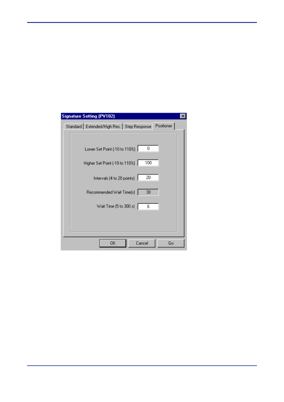
• Measurement Setting Parameters
Figure 14.16 Poitioner Signature Setting
The measurement setting parameters consist of five float arrays.
Lower Set point signal (%): It determines input signal to start the measurement
Higher Set point signal (%): It determines the highest input signal in the measure-
ment.
Intervals (points): Intervals determine the measurement points of this signature
function. Width of measurement point is determined in equation below. The valid range
is 4 to 20 points.
Width = (Higher Set point signal – Lower Set point signal)/Intervals
Total Sample points (collected in round trip)=2*Intervals+1
Recommended wait time (sec): It can be used as a guide for setting wait time (read
only).
Wait time (sec): It determines the data acquisition queuing time for each measure-
ment. The valid range is 5 to 300 seconds.