Warning – Yokogawa YVP20S User Manual
Page 107
10-9
IM 21B04C50-01E
<10. CALIBRATION SERVICES>
Step 2 Select 0% Calibration. Move the valve by entering a value in the Current
Target Position (Change To) text box, and clicking Set, until the valve is in the
desired closed position. The valve can be jogged by selecting the Increment
change amount (0.1 for example, in Figure 10.9) and by clicking the up or
down arrow beside the Change to (%) text box. Click once and wait until the
position value shows the change. Repeat until the valve is at the desired 0%
position. (It is not necessary to click Set, when using the increment arrows.)
Step 3 When the valve is in the closed position click the Apply Calib. Button. A dialog
appears to confirm that you want to apply the calibration. Click Yes.
Step 4 Select Span Calibration. Change the Current Target Position value by entering
a number or by incrementing until the valve is in the desired 100% open
position, using the same procedure as in Step 2 .
Step 5 When the valve is in the open position (refer to the mechanical travel indicator
on the valve), click the Apply Calib. Button. A dialog appears to confirm that
you want to apply the calibration. Click Yes.
Step 6 To apply a correction for non-linearity, select 50% Calibration. Move the valve
until it is at the mechanically indicated 50% position, using the same procedure
as in Step 2 .
0
10
20
30
40
50
60
70
80
90
100
10.00
8.00
6.00
4.00
2.00
0.00
setpoint (%)
Correction Applied (%)
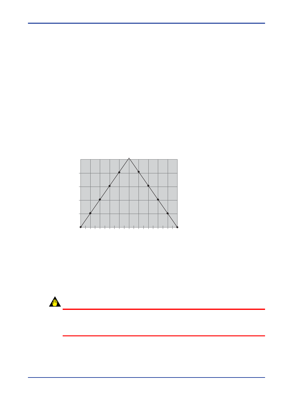
Percent non-linearity error
50% corrected to 60%
F1010
Figure 10.10 Non-linearity Travel Correction
Step 7 When the valve is at the desired 50% position (refer to the mechanical travel
indicator on the valve), click the Apply Calib. Button. A dialog appears to
confirm that you want to apply the calibration. Click Yes. This provides non-
linearity correction with two line segments as shown in Figure 10.10, in which
“55” was entered in the Current Target Position. Note that 55 is an extreme
correction!
WARNING
Applying a correction to the 0% and 100 % position calibration may alter the effect of other
limits and settings. For example, the Tight Shutoff Below and Full Open Above parameter
may need to be re-configured.