2 function block links, Function block links -3 – Yokogawa YVP20S User Manual
Page 32
5-3
IM 21B04C50-01E
<5. FOUNDATION FIELDBUS OVERVIEW>
5.1.2
Function block links
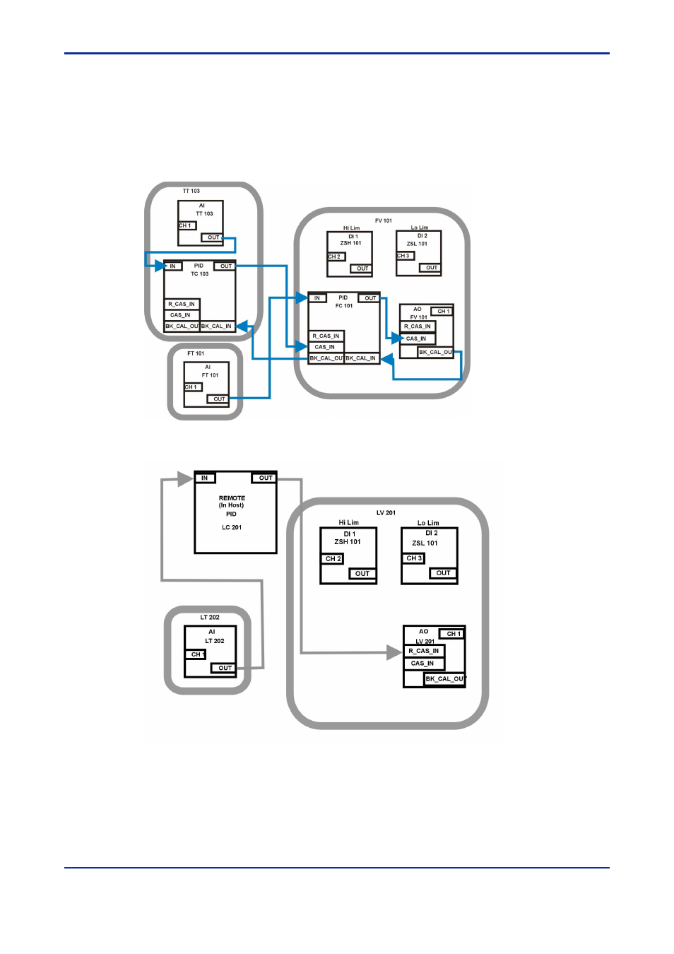
Each of the control functions is represented in the Control configuration as Foundation
fieldbus Function Blocks. All the blocks in the temperature cascade are shown in Figure
5.3. They are grouped according to the physical device containing them, and they are
shown with the links between the blocks (“soft wiring” connections) for data flow.
Similarly, the level loop function blocks are shown in Figure 5.4.
Figure 5.3 Temperature Cascade Block Diagram
Figure 5.4 Level loop block diagram