Explanation of basic items, 1 outline, 3 lcd transducer block – Yokogawa FVX110 User Manual
Page 44: 1 function outline, 2 operating mode, 3 indicator names and functions, Explanation of basic items -1, Outline -1, Lcd transducer block -1 7.3.1, Function outline -1
<7. Explanation of Basic Items>
7-1
IM 01S01C01-01EN
7. Explanation of Basic Items
7.1 Outline
This chapter provides an outline of the LCD
transducer block and describes basic parameter
setup procedures. For information on function
blocks as well as the LM function and software
download functions, refer to Appendix 1 to 8.
7.2 Setting and Changing
Parameters for the Whole
Process
IMPORTANT
Do not turn off the power immediately after
making a setting. When data is saved to the
EEPROM, redundant processing is performed
to enhance reliability. If the power is turned off
within 60 seconds after making a setting, the
modified parameters are not saved and may
return to their original values.
Operating mode
Many parameters require a change of operating
mode of the function block to O/S (Out of Service)
to rewrite parameter data. To change the operating
mode of the function block, its MODE_BLK needs
to be changed. The MODE_BLK is comprised of
the four sub-parameters below:
(1) Target (target mode):
Parameter to set the operating mode of the
block.
(2) Actual (Actual mode):
Parameter to indicate the current operating
mode of the block.
(3) Permit (Permitted mode):
Parameter to indicate operating mode that the
block is allowed to take.
(4) Normal (Normal mode):
Parameter to indicate the operating mode the
block will usually take.
7.3 LCD Transducer Block
7.3.1 Function Outline
The LCD transducer block controls the indications
displayed on the LCD. FVX110 displays process
variables from field instruments which have
received in MAO or IS function block and also
simulation input.
7.3.2 Operating mode
The operating conditions permitted for the LCD
transducer block are Automatic (AUTO) and Out
of Service (O/S) mode. Settings can normally
be changed in the O/S mode, but can also be
performed in the Auto mode except for changes of
the block tag parameter of the block header in the
LCD transducer block.
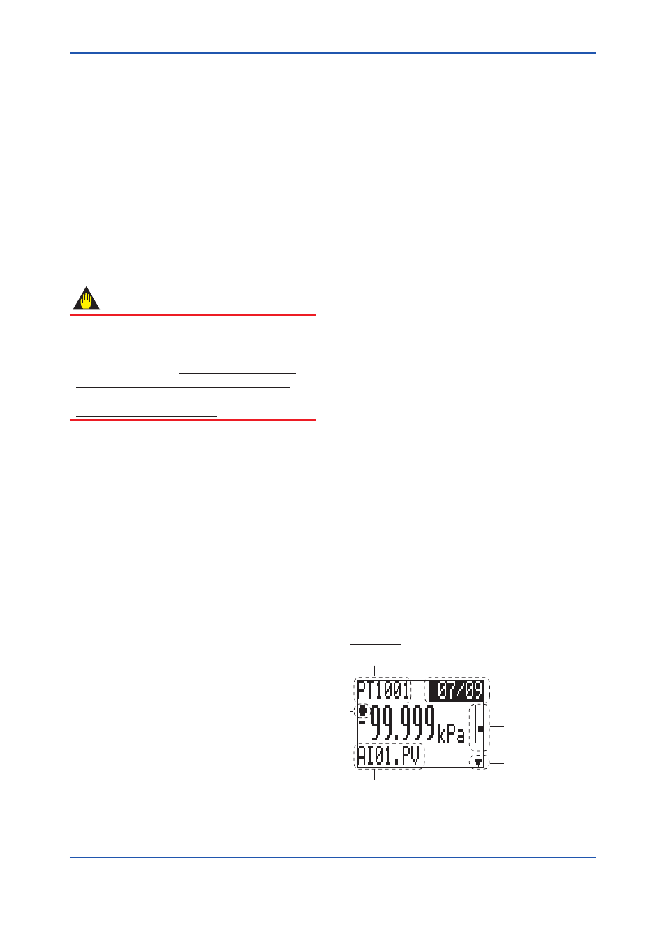
7.3.3 Indicator names and functions
The LCD consists of three fields: the top, center
and bottom fields. The top field shows the Main
Tag which identifies the instrument whose values
are indicated (for example PD_Tag), and other
freely settable information. It also shows the page
information (number of displayed page)/(total
number of display pages). The middle field shows
process value and measuring unit. The lower
field shows the Sub Tag, a field indicating data
required for identifying instruments whose values
are displayed, communication status, bar graph
and other information. At the center right edge,
there is a scroll bar enabling visual confirmation
of page numbers. The lower right corner displays
an icon indicating the scroll knob turning direction
and the center left edge provides an icon indicating
communication status.
F0701.ai
Page information
display
Scroll bar
Scroll knob
turning direction
Sub tag, communication
status bar graph (selected display)
Main Tag
The communication signal
Figure 7.1 Display design