4 grounding, 5 connection of devices, Grounding -3 – Yokogawa FVX110 User Manual
Page 30: Connection of devices -3
<5. Installation>
5-3
IM 01S01C01-01EN
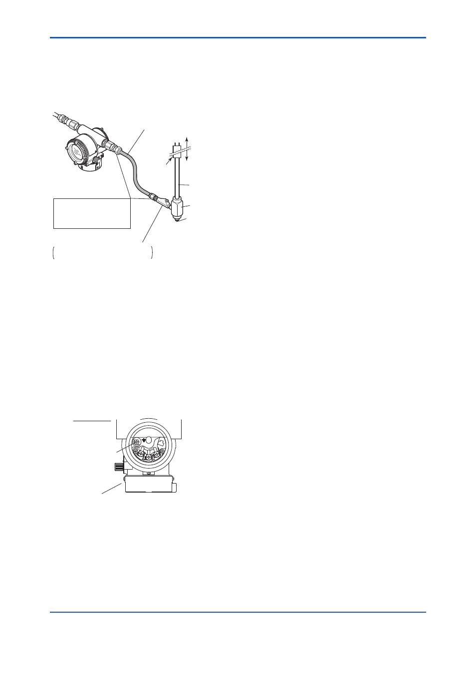
■ Flameproof metal conduit wiring
• A seal fitting must be installed near the terminal
box connection port for a sealed construction.
• Apply a non-hardening sealant to the threads of
the terminal box connection port, flexible metal
conduit and seal fitting for waterproofing.
F0504.ai
Non-hazardous
area
Hazardous area
Flameproof
heavy-gauge
steel conduit
Tee
Drain plug
Seal fitting
Gas sealing
device
Flameproof flexible
metal conduit
Apply a non-hardening
sealant to the threads of
these fittings for
waterproofing
After wiring, impregnate the fitting
with a compound to seal tubing.
Figure 5.4
Typical Wiring Using Flameproof Metal
Conduit
5.4 Grounding
Grounding is always required for the proper
operation of indicator. Follow the domestic electrical
requirements as regulated in each country. For a
indicator with a built-in lightning protector, grounding
should satisfy ground resistance of 10Ω or less.
Ground terminals are located on the inside and
outside of the terminal box. Either of these terminals
may be used.
F0505.ai
SUPPL
Y
PULSE
CHECK
ALARM
Ground terminal
(inside)
Ground terminal
(outside)
Terminal box
Figure 5.5
Ground Terminals
5.5 Connection of Devices
The following are required for use with Fieldbus
devices:
• Power supply:
Fieldbus requires a dedicated power supply. It
is recommended that current capacity be well
over the total value of the maximum current
consumed by all devices (including the host).
Conventional DC current cannot be used as is.
• Terminator:
Fieldbus requires two terminators. Refer to
the supplier for details of terminators that are
attached to the host.
• Field devices:
Connect Fieldbus communication type field
devices. Two or more EJX, YTA, AXF or other
devices can be connected.
• Host:
Used for accessing field devices. A
dedicated host (such as DCS) is used for
an instrumentation line while dedicated
communication tools are used for experimental
purposes. For operation of the host, refer to
the instruction manual for each host. No other
details on the host are given in this manual.
• Cable:
Used for connecting devices. Refer to “Fieldbus
Technical Information” (TI 38K03A01-01E)
for details of instrumentation cabling. For
laboratory or other experimental use, a twisted
pair cable two to three meters in length with a
cross section of 0.9 mm
2
or more and a cycle
period of within 5 cm (2 inches) may be used.
Termination processing depends on the type
of device being deployed. For FVX110, use an
M4 screw terminal claw. Some hosts require a
connector.
Refer to Yokogawa when making arrangements to
purchase the recommended equipment.
Connect the devices as shown in Figure 5.6.
Connect the terminators at both ends of the
trunk, with a minimum length of the spur laid for
connection.
The polarity of signal and power must be
maintained.