Yokogawa FVX110 User Manual
Page 18
<2. Handling Cautions>
2-8
IM 01S01C01-01EN
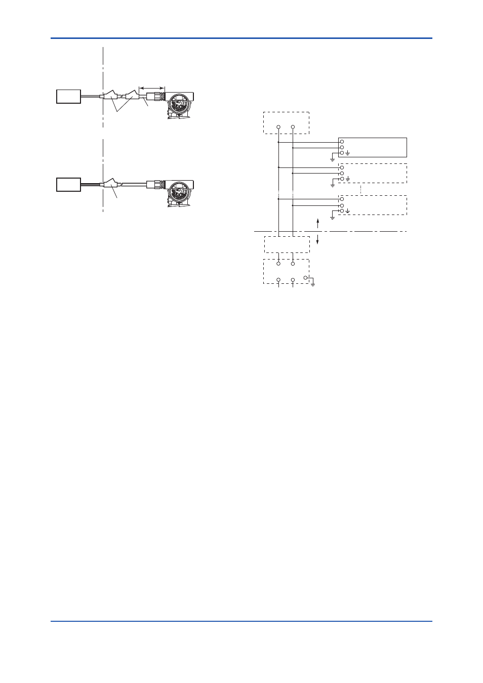
Non-hazardous
Location
Equipment
32 V DC Max.
15 mA DC
Signal
Non-Hazardous
Locations
Hazardous Locations Division 1
Non-Hazardous
Locations
Hazardous Locations Division 2
50 cm Max.
Sealing Fitting
Conduit
Non-hazardous
Location
Equipment
32 V DC Max.
15 mA DC
Signal
Sealing Fitting
F0206.ai
SUPPLY
PULS
E
CHECK
ALARM
SUPPLY
PULSE
CHECK
ALARM
SUPPL
Y
PUL
SE
CHECK
ALARM
SUPPL
Y
PUL
SE
CHECK
ALARM
Segment Indicator
Segment Indicator
b. CSA Intrinsically safe and Nonincendive
Type
FVX110 Fieldbus Segment Indicator with
optional code /CS15.
• Certificate: 2346277
• Applicable standard:
C22.2 No.0, C22.2 No.0.4, C22.2 No.25,
C22.2 No.94, C22.2 No.157, C22.2 No.213,
C22.2 No.61010-1-04, C22.2
CAN/CSA E60079-0, CAN/CSA E60079-11,
CAN/CSA E60079-15, IEC 60529
• CSA Intrinsically Safe Approval
Class I, Division 1, Groups A, B, C, & D;
Class II, Division 1, Groups E, F & G;
Class III Division 1; Ex ia IIC T4
Ambient Temperature: –40* to 60°C (–40* to
140°F) Encl. Type 4X, IP66 and IP67
* –15ºC when O-ring material is Fluoro-rubber.
• CSA Nonincendive Approval
Class I, Division 2, Groups A, B, C, & D;
Class II, Division 2, Groups F & G;
Class III Division 1; Ex nL IIC T4
Ambient Temperature: –40* to 60°C (–40* to
140°F) Encl. Type 4X, IP66 and IP67
* –15ºC when O-ring material is Fluoro-rubber.
● Caution for CSA Intrinsically safe type.
(Following contents refer to “DOC. No.
ICS018”)
Installation Diagram for Intrinsically safe
(Division 1 Installation)
Non-Hazardous Location
Hazardous Location
F0207.ai
Terminator
Safety Barrier
Field Instruments
Indicator
Field Instruments
+
–
+
–
+
–
Terminator
+
–
+
–
Note 1. The safety barrier must be CSA certified.
Note 2. Input voltage of the safety barrier must be
less than 250Vrms/Vdc.
Note 3. Installation should be in accordance with
Canadian Electrical Code Part I and local
Electrical Code.
Note 4. Do not alter drawing without authorization
from CSA.