4 setting of tags and addresses, 5 communication setting, 1 vcr setting – Yokogawa FVX110 User Manual
Page 37: Setting of tags and addresses -4, Communication setting -4 6.5.1, Vcr setting -4
<6. Configuration>
6-4
IM 01S01C01-01EN
6.4 Setting of Tags and
Addresses
This section describes the steps in the procedure
to set PD Tags and node addresses in the FVX110.
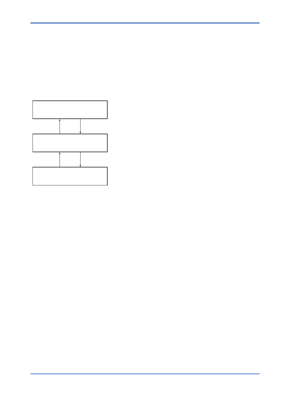
There are three states of Fieldbus devices as
shown in Figure 6.4, and if the state is other than
the lowest SM_OPERATIONAL state, no function
block is executed. FVX110 must be transferred
to this state when an FVX110 tag or address is
changed.
UNINITIALIZED
(No tag nor address is set)
Tag clear
Tag setting
INITIALIZED
(Only tag is set)
SM_OPERATIONAL
(Tag and address are retained, and
the function block can be executed.)
Address clear
F0604.ai
Address setting
Figure 6.4
Status Transition by Setting PD Tag and
Node Address
FVX110 has a PD Tag (UT1001) and node
address (245, or hexadecimal F5) that are set
upon shipment from the factory unless otherwise
specified. To change only the node address, clear
the address once and then set a new node address.
To set the PD Tag, first clear the node address and
clear the PD Tag, then set the PD Tag and node
address again.
Devices whose node addresses have been cleared
will have the default address (randomly chosen
from a range of 248 to 251, or from hexadecimal
F8 to FB). At the same time, it is necessary to
specify the device ID in order to correctly specify
the device. The device ID of the FVX110 is
5945430010xxxxxxxx. (The xxxxxxxx at the end
of the above device ID is a total of 8 alphanumeric
characters.)
6.5 Communication Setting
To set the communication function, it is necessary
to change the database residing in SM-VFD.
6.5.1 VCR Setting
Set VCR (Virtual Communication Relationship),
which specifies the called party for communication
and resources. FVX110 has 35 VCRs whose
application can be changed, except for the first
VCR, which is used for management.
FVX110 has VCRs of four types:
Server(QUB) VCR
A Server responds to requests from a host. This
communication needs data exchange. This
type of communication is called QUB (Queued
User-triggered Bidirectional) VCR.
Source (QUU) VCR
A Source multicasts alarms or trends to other
devices. This type of communication is called
QUU (Queued User-triggered Unidirectional)
VCR.
Publisher (BNU) VCR
A Publisher multicasts AI block output of field
device to another function block(s). This type
of communication is called BNU (Buffered
Network-triggered Unidirectional) VCR.
Subscriber (BNU) VCR
A Subscriber receives output of another
function block(s) by MAO block or PID block.
A Server VCR is capable to responding to
requests from a Client (QUB) VCR after the Client
successfully initiates connection to the Server. A
Source VCR transmits data without established
connection. A Sink (QUU) VCR on another device
can receive it if the Sink is configured so. A
Publisher VCR transmits data when LAS requests
so. An explicit connection is established from
Subscriber (BNU) VCR(s) so that a Subscriber
knows the format of published data.
Each VCR has the parameters listed in Table 6.4.
Parameters must be changed together for each
VCR because modification of individual parameters
may cause inconsistent operation.