A5.2.3 converting accumulation, A5.2.4 determining the input flow direction, A5.2.3 converting – Yokogawa digitalYEWFLO (DY-FF) User Manual
Page 99: Accumulation, A5-3, A5.2.4
A5.2.3 Converting
Accumulation
This following describes an example of
accumulation conversion.
In accumulation conversion, the difference between
the value executed previously and the value
executed this time is integrated or accumulated.
This conversion applies when the output of a
function block used as a counter is input to the input
process of the Integrator block.
In order to convert the rate of change of an input
to a value with an engineering unit, the user must
confi gure the factor of conversion to the appropriate
engineering unit in the PULSE_VAL1 and PULSE_
VAL2 parameters.
Moreover, the unit of IN_2 is standardized to that
of IN_1 in the same way as rate conversion. Thus,
the user must also set an appropriate value to
UNIT_CONV.
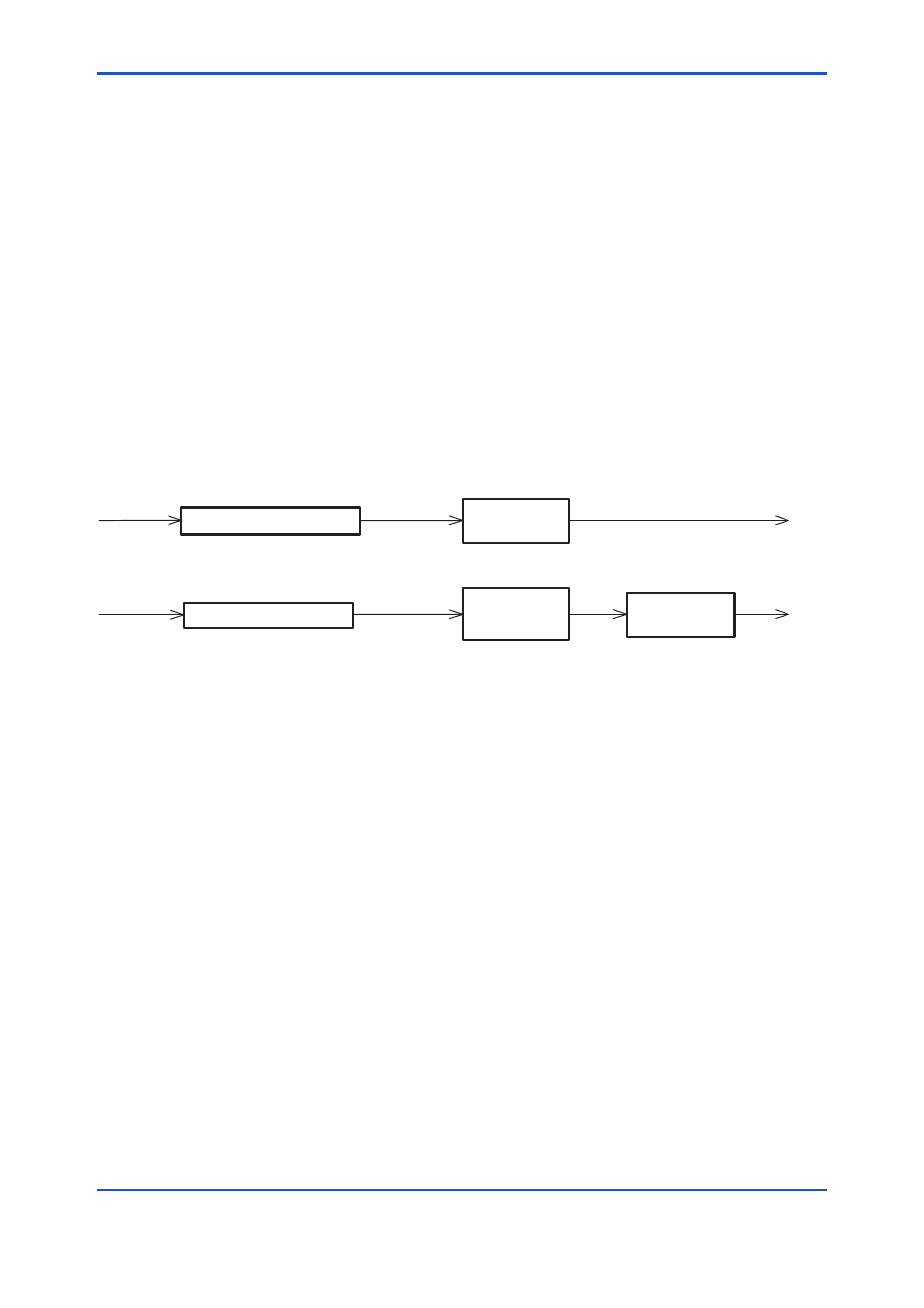
input1
counts
number of pulse
kg
kg/pulse
increment1
increment2
lb/pulse
input2
counts
number of pulse
lb
kg
[Current read value] – [Previous read value]
[Current read value] – [Previous read value]
PULSE_VAL1(#19)
× [pulse value1]
PULSE_VAL2(#20)
× [pulse value2]
UNIT_CONV(#18)
× [conversion factor]
FA0503.ai
Figure A5.3 Increment Calculation with Counter Input
A5.2.4 Determining the Input Flow
Direction
The Integrator block also considers the input fl ow
direction. Information about the input fl ow direction
is contained in REV_FLOW1 and REV_FLOW2 (0:
FORWARD, 1: REVERSE).
In input processing, the sign of the value after rate
and accumulation conversion is reversed if the
REV_FLOW1 and REV_FLOW2 parameters are
set to REVERSE. When determination of the fl ow
direction of two input values is complete, these
two inputs are passed to the adder. The settings in
REV_FLOW will be retained even if the power is
turned OFF.
A5-3
IM 01F06F00-01EN